|
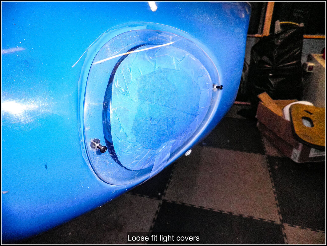
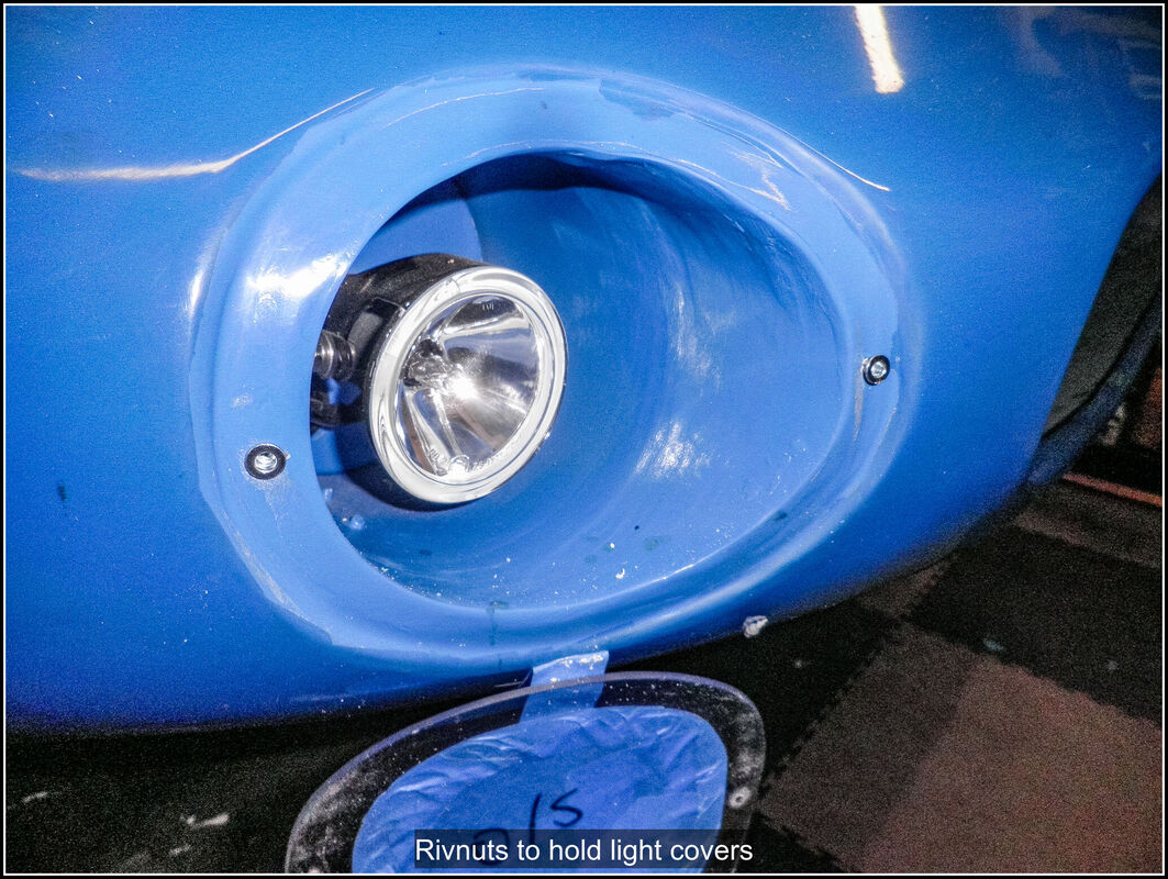
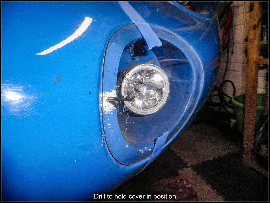
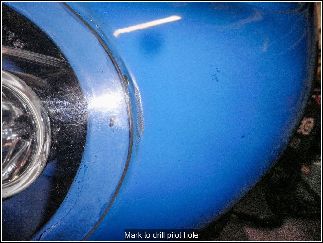
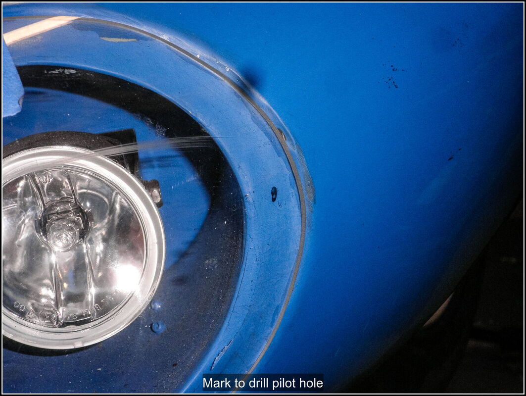
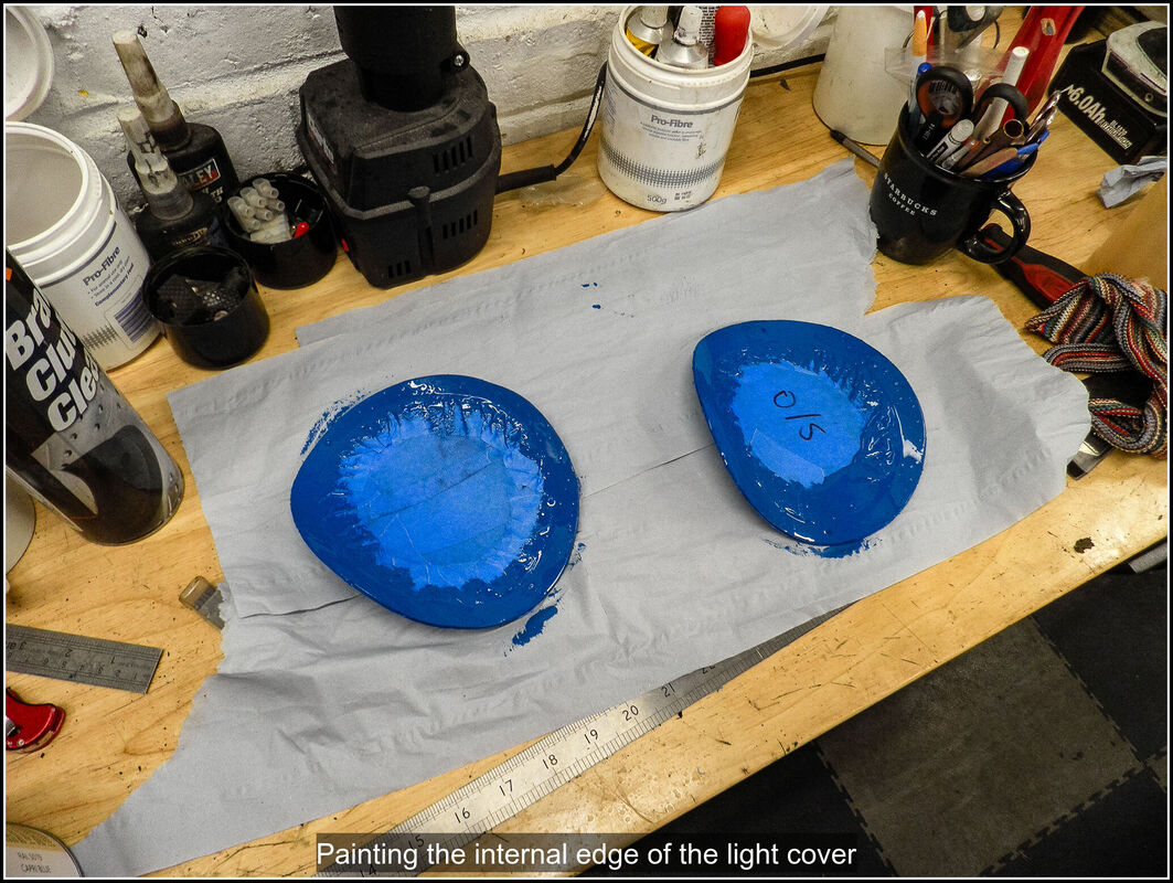
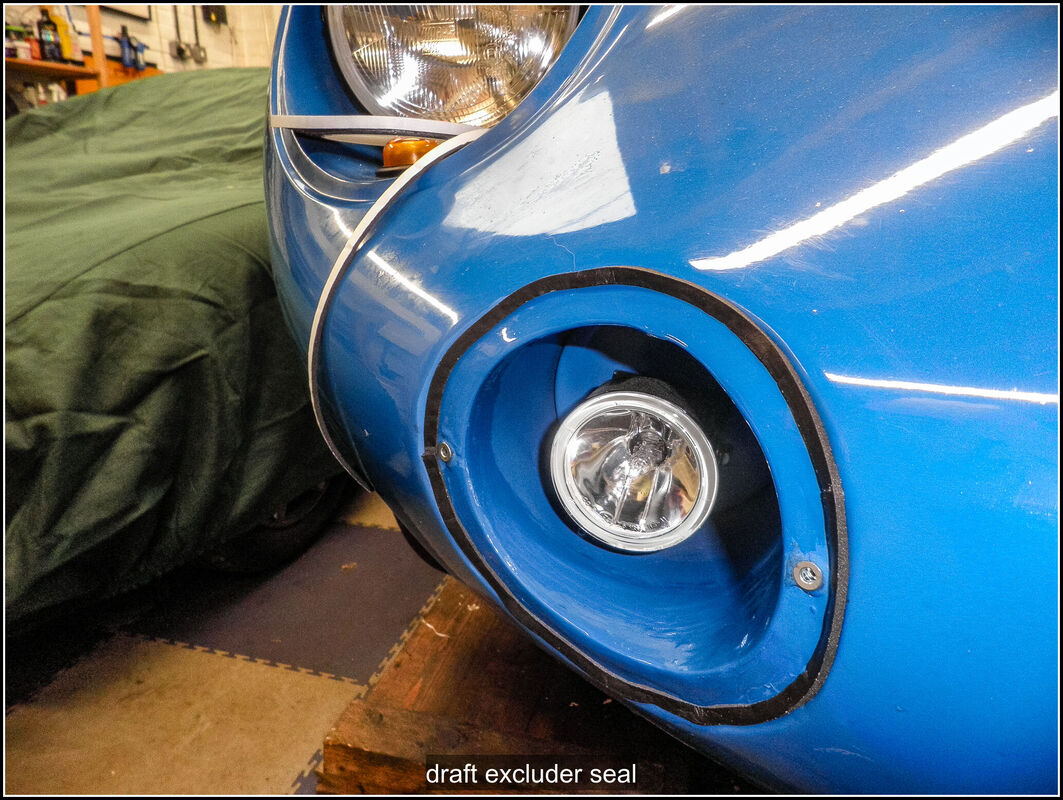
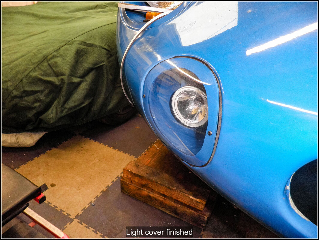
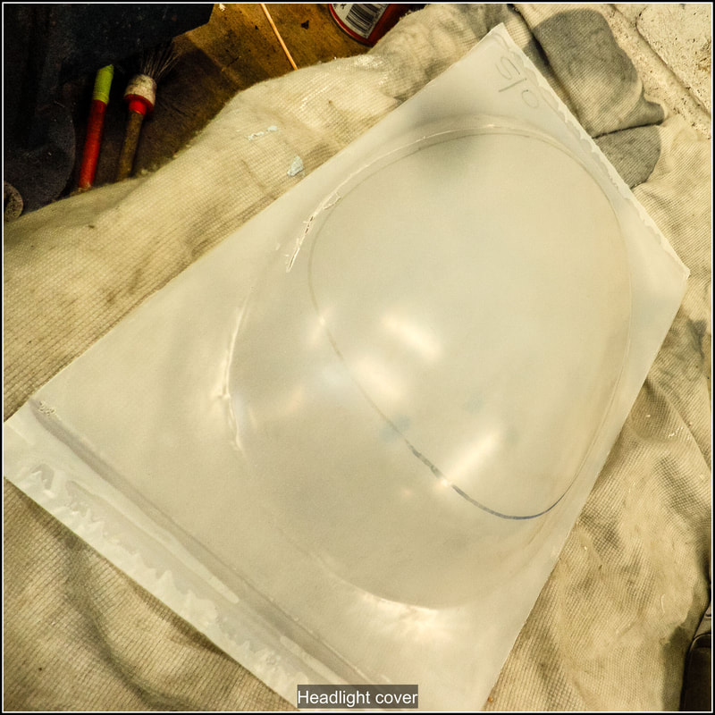
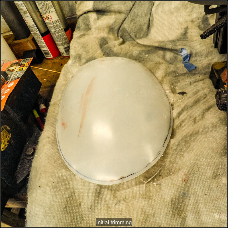
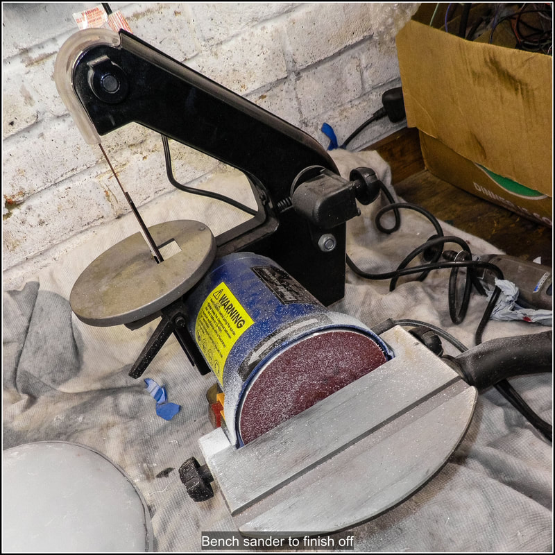
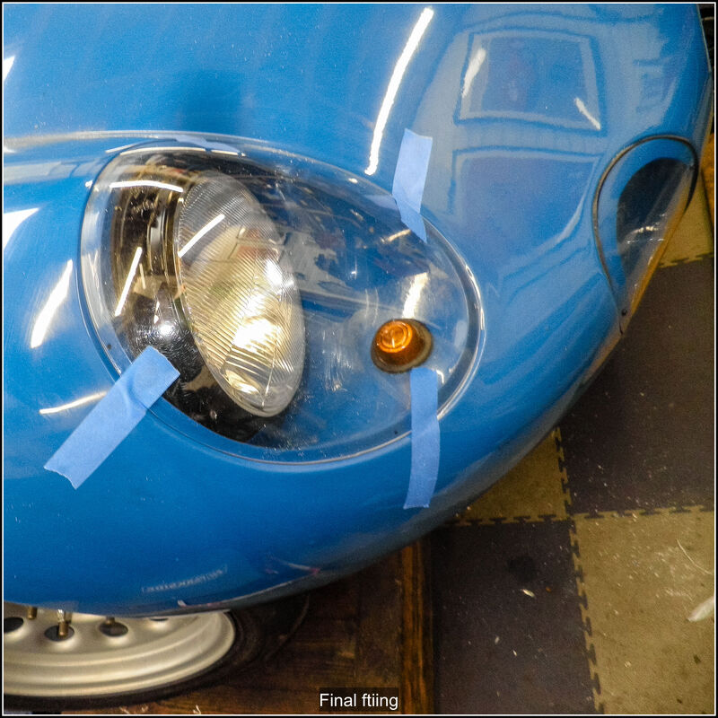
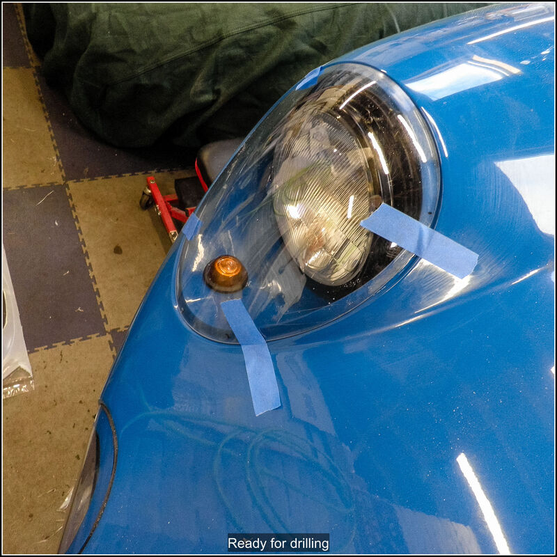
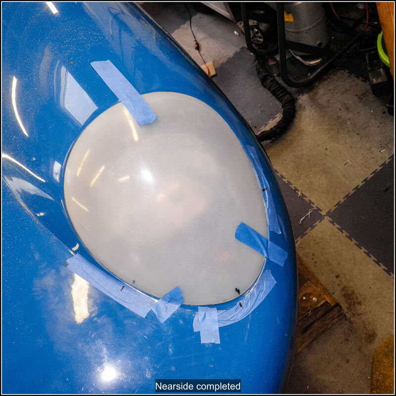
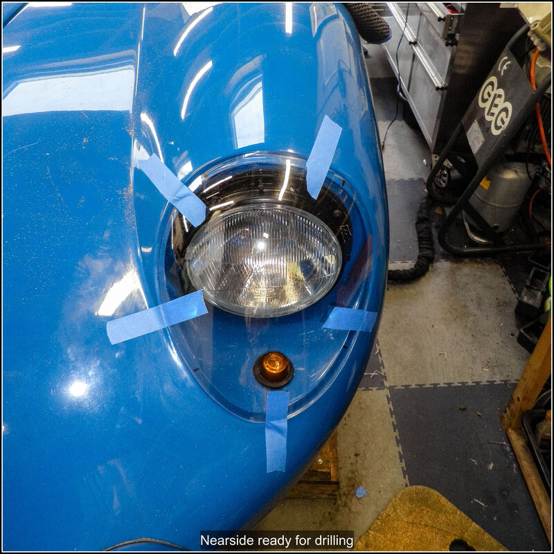
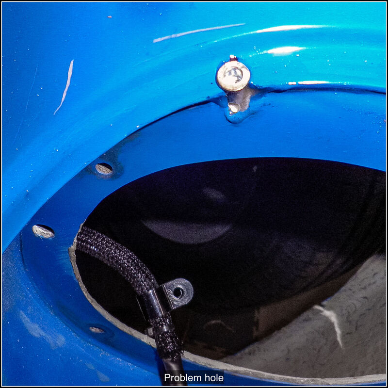
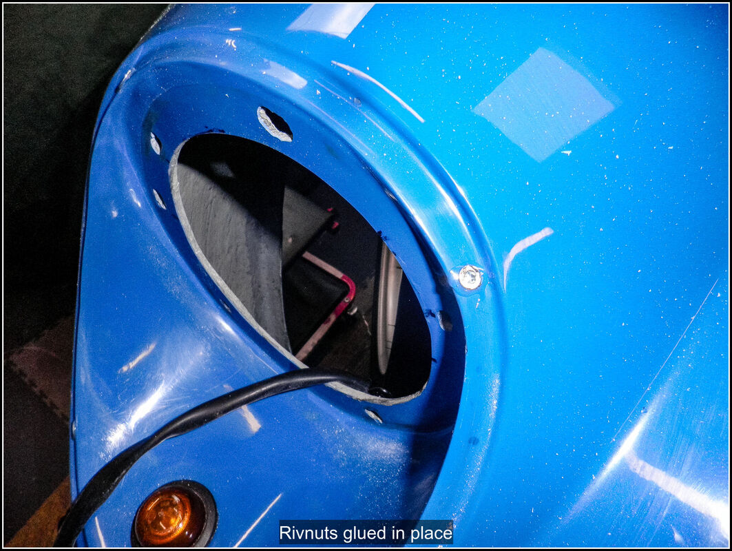
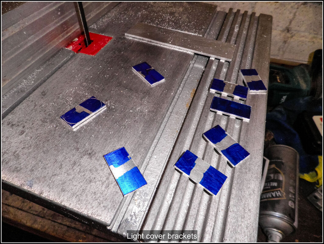
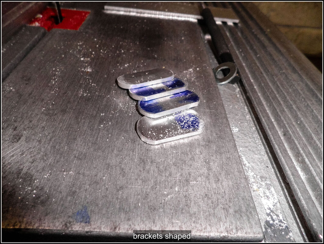
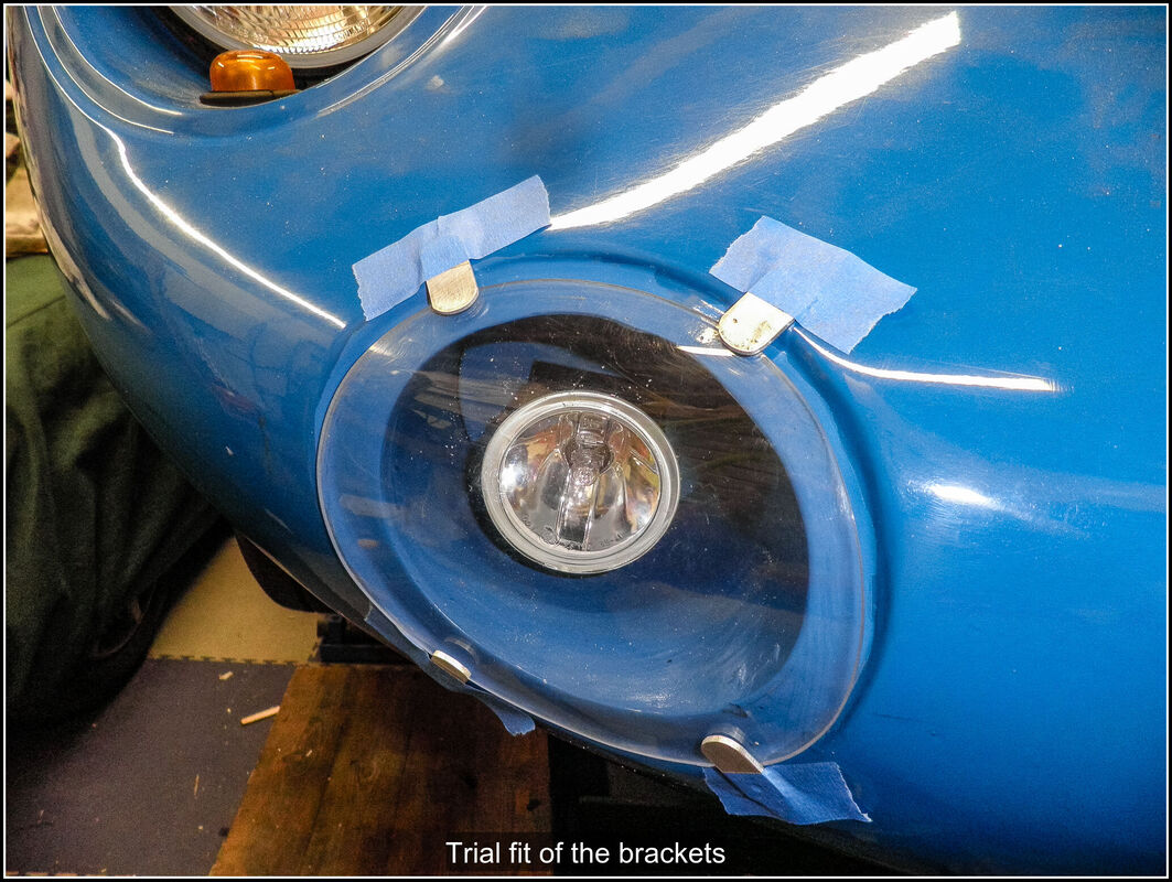
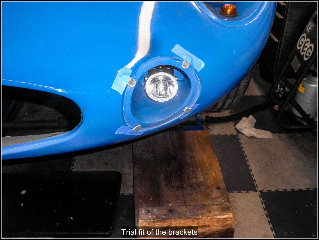
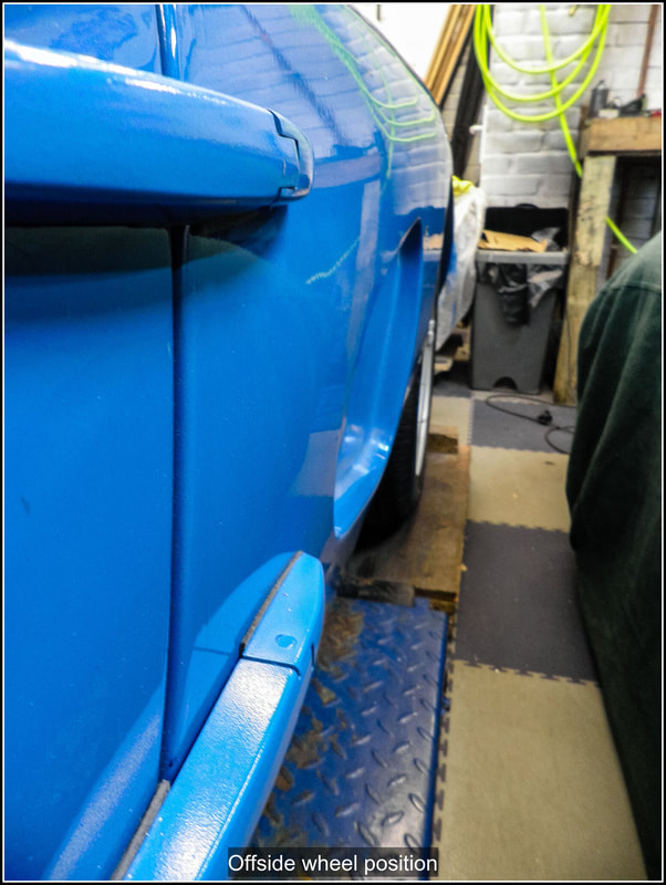
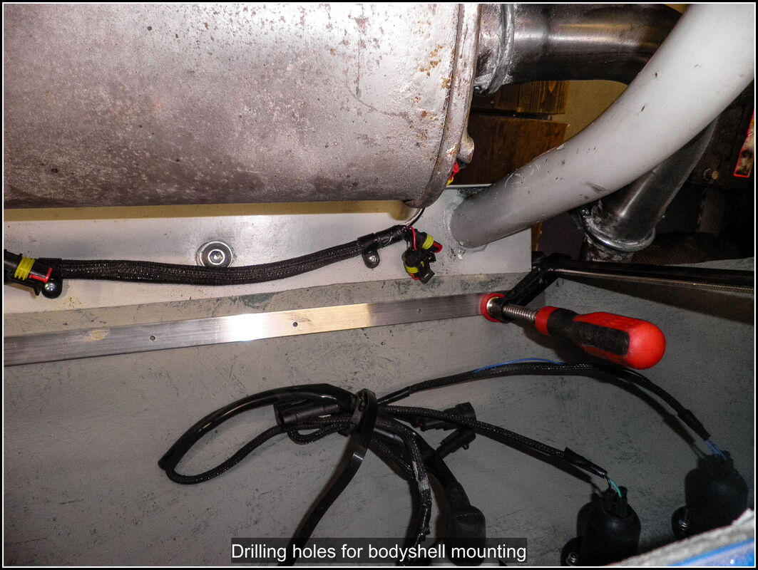
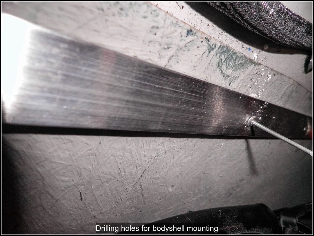
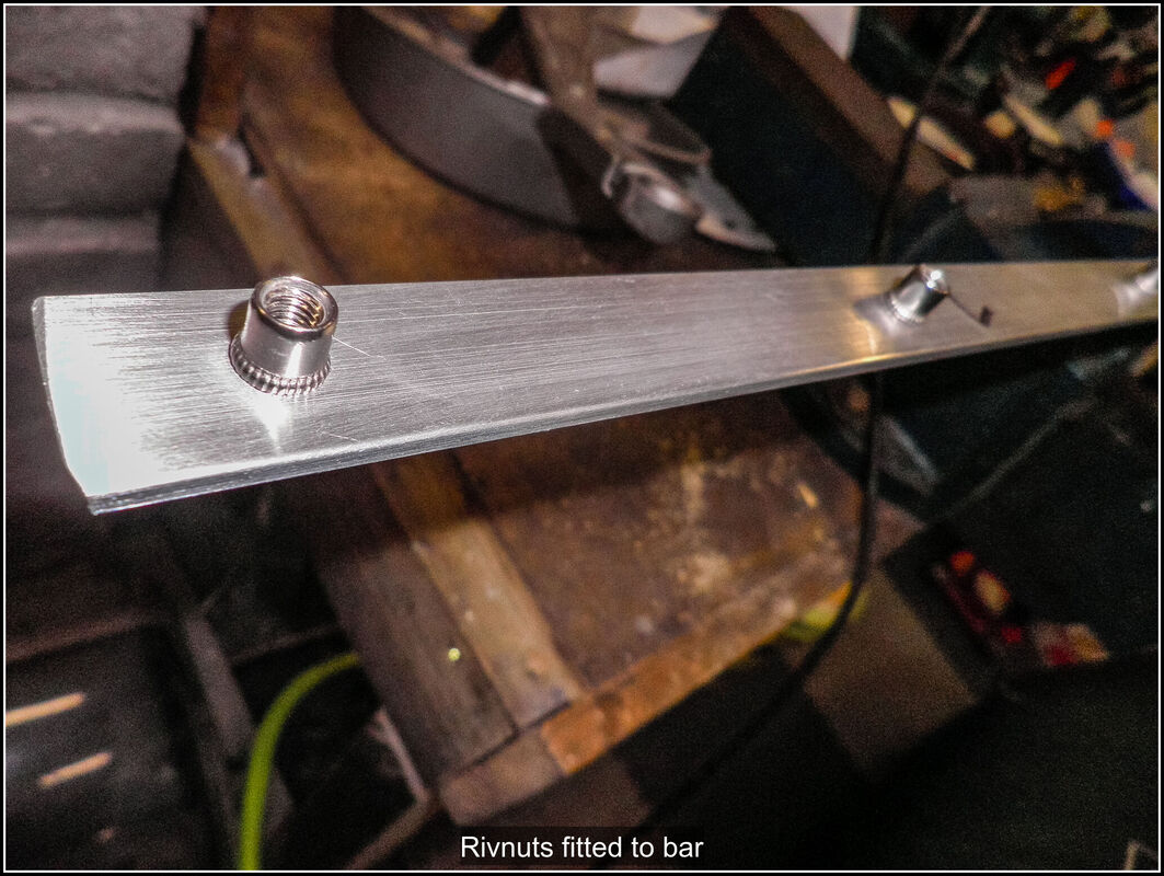
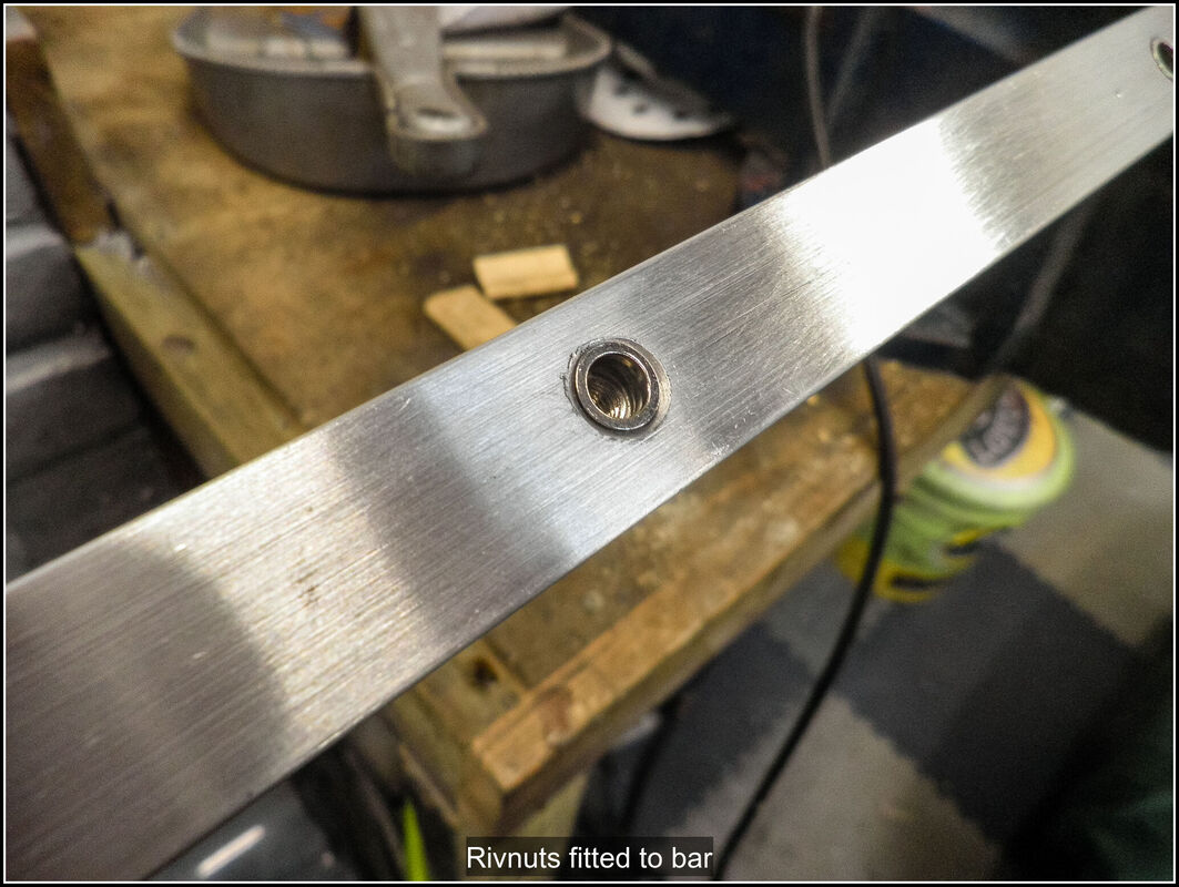
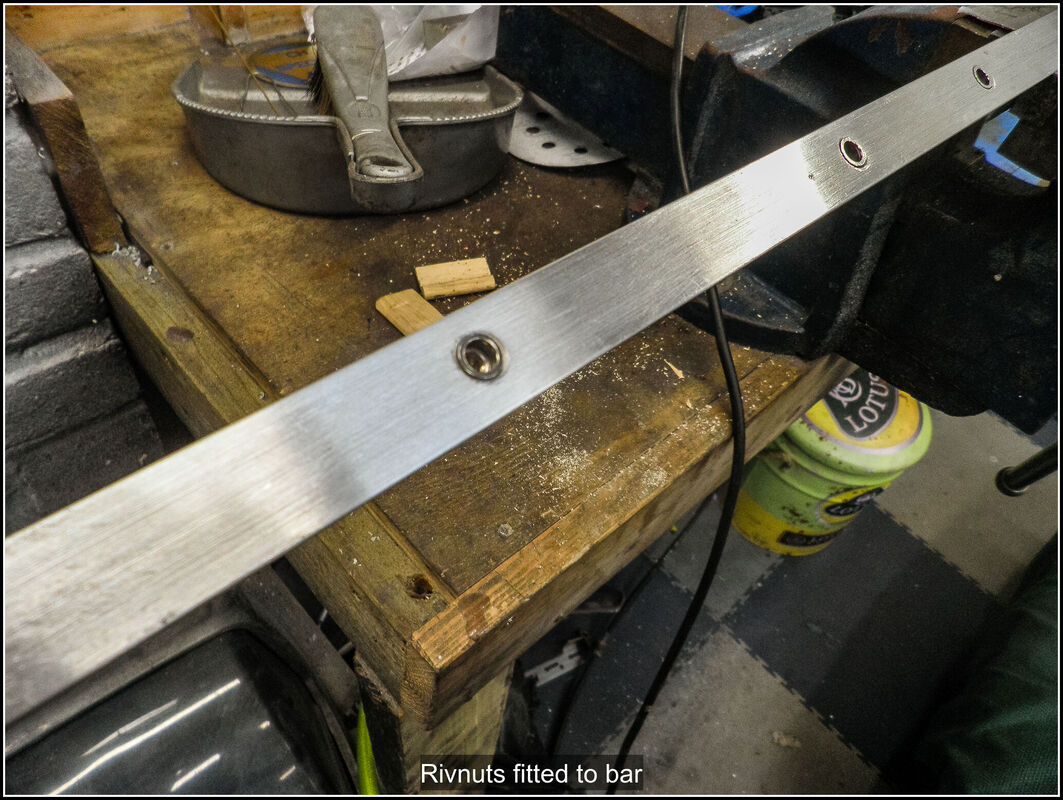
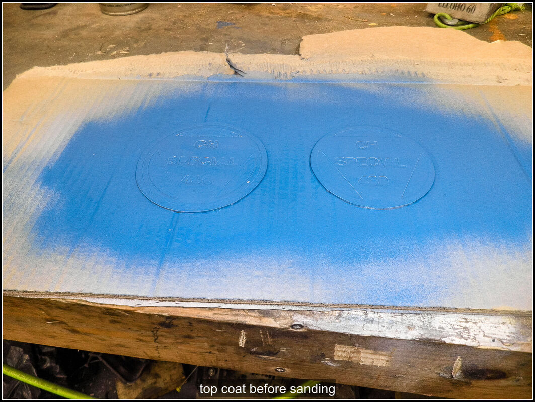
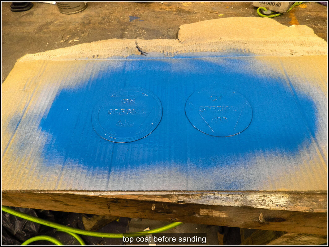
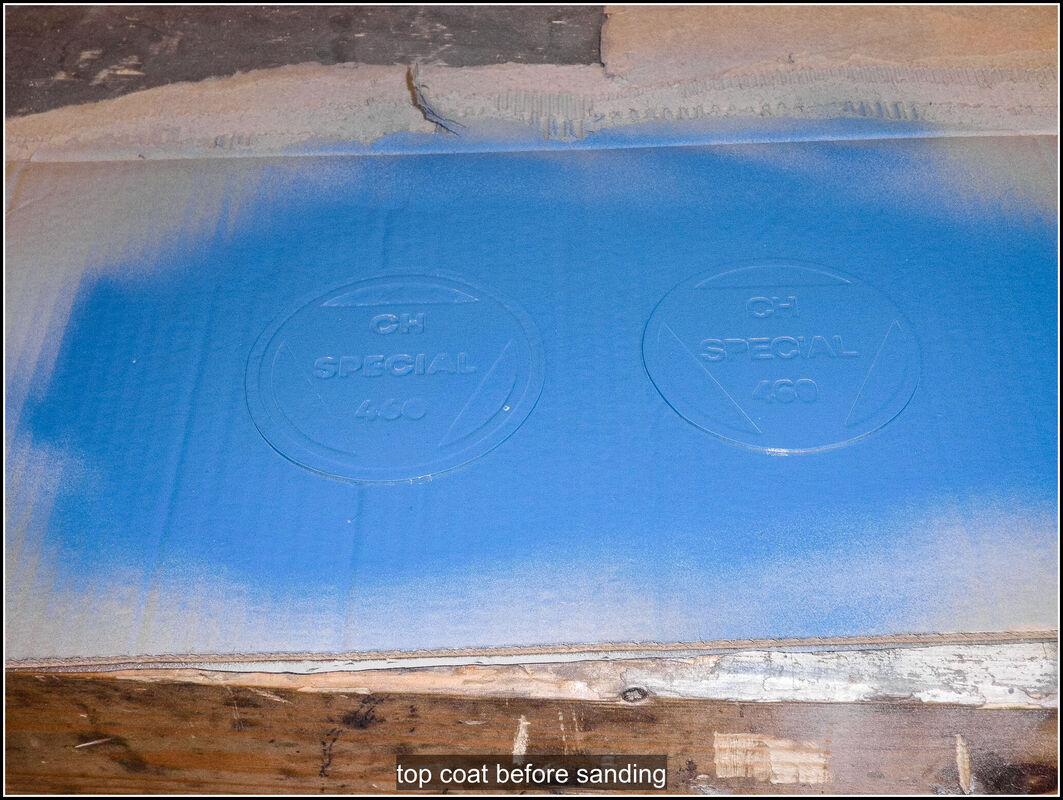
19 February 2024 Wow, it's already ahalfway through February and this is my first post of 2024! The Replicar has taken a bit of a backseat over the last few months. A few of my family's cars have needed my attention, and my other weekend car (TVR Griffith) has been treated to some tlc recently. To ease myself back into the kit I started with something easy and decided to work on the driving light covers. I'd made the covers a long time ago but procrastinated how to secure them to the car. After a few test fits, I settled on glueing some rivnuts into the body of the car (I didn't like the idea of trying to compress them into the GRP) and screwing the covers on that way. I spent some time deciding how many to use and where to position them. This was mostly dictated by the space behind the body where the rivnuts would go. In the end I settled on two fixings spaced horizontally, M3 alloy rivnuts and dome headed cap screws. I marked the body where I was drilling and then put the cover in place, secured with tape, and drilled through both at the same time. I put a drill bit in the first hole to keep the alignment and drilled the second hole. I drilled the hole in the body to take the rivnut body and then glued them in position with epoxy. Once the epoxy set, I test fitted everything again. I wanted to paint the inside of the lens round the edge to smarten it up a bit. I applied masking tape to the inside face of the cover and also on the outside round the edge and then brushed on some body colour enamel, I also touched up the apertures on the car. 21 February 2024 Once the paint was dry I applied some small closed cell draft excluder round the edge of the aperture on the car and scrwed the covers in place. I adjusted the position of the excluder to try and even out the edge. Very satisfied with how they turned out. Flushed with that success I got the main headlight covers down and roughly cut the offside cover out, I assumed the line drawn on the cover was a rough representation of the size required so I was fairly generous and started to bring it down to the right dimension with my bench sander. 23 February 2023 Finished sanding the offside headlight cover and taped into position. I then did the same for the nearside cover. With them both in place I drilled out 3.2mm holes through the cover into the body. This mostly went OK but a couple of holes broke through the side of the lamp recess. I removed the headlights and bowls so I could get to the holes that broke through. I glued the rivnuts into the holes with a bit extra to fill in the bits that broke through. I'll have to sand those down and touch them up with some paint, once the glue has dried.
0 Comments
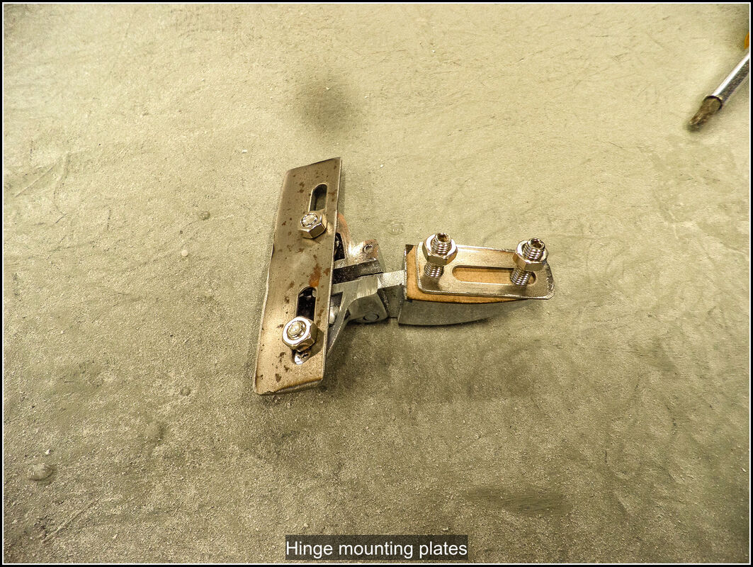
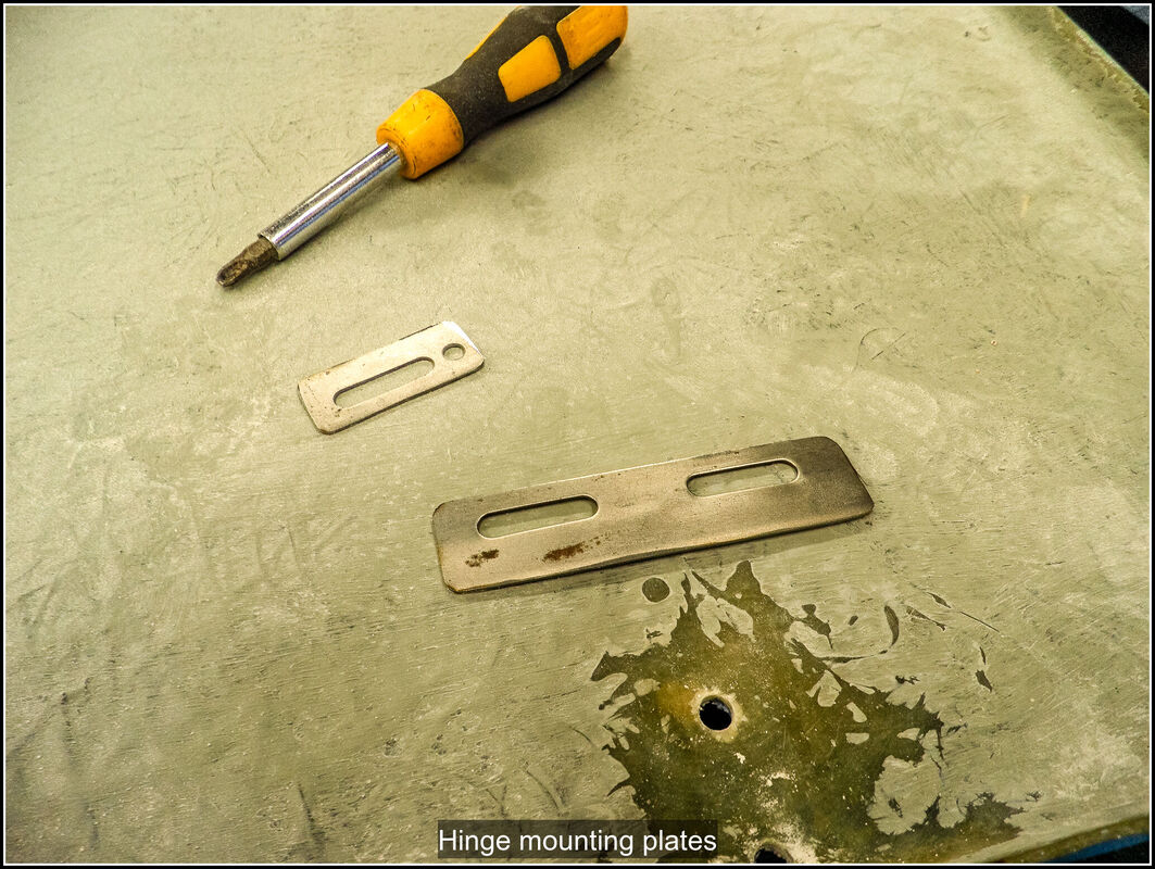
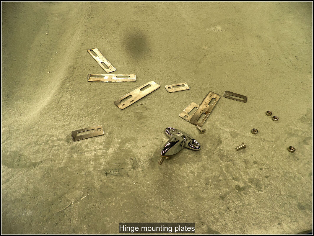
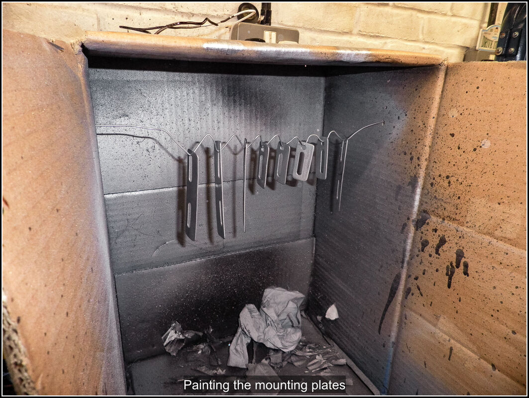
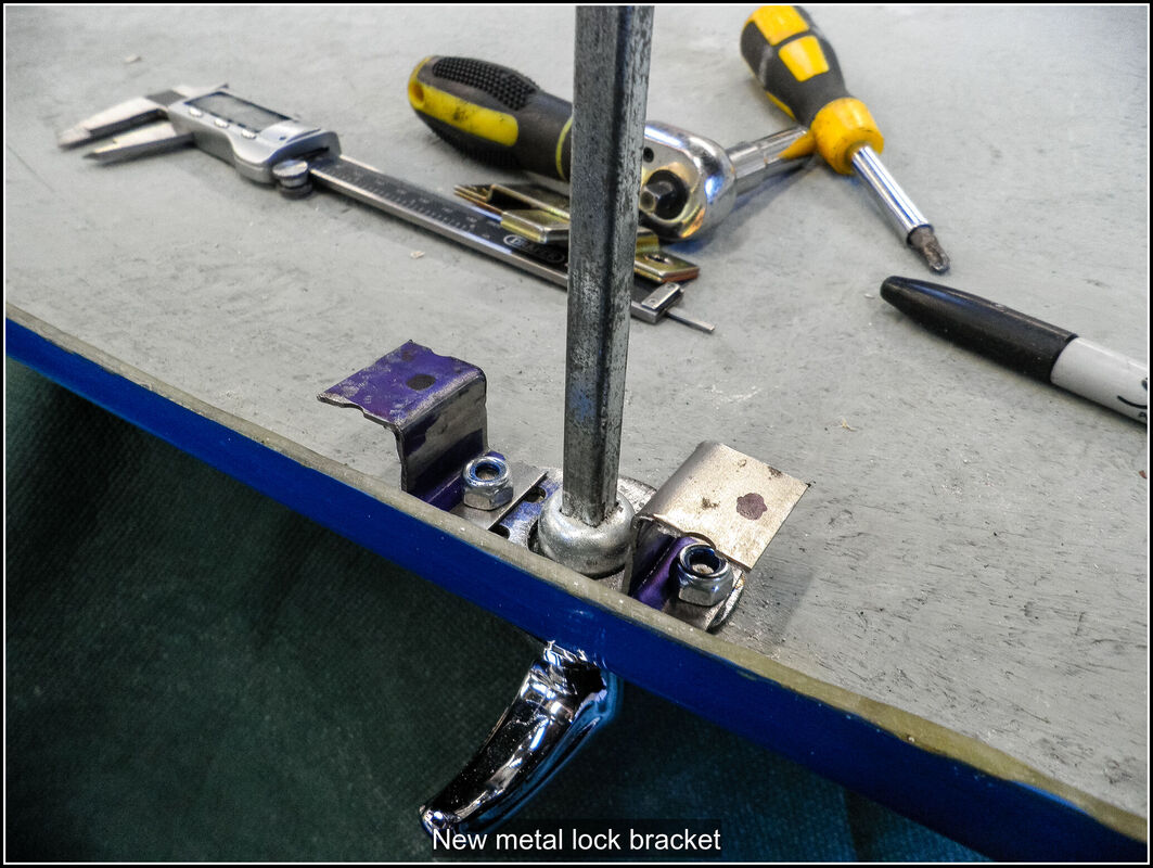
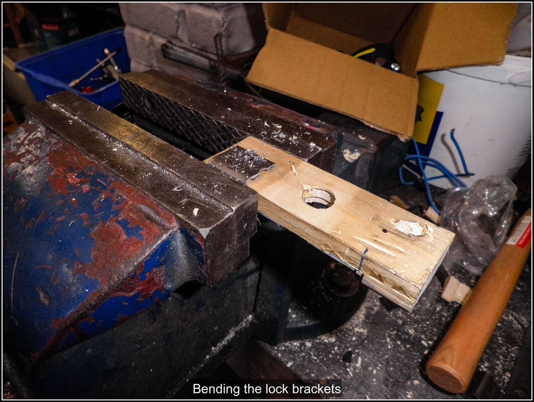
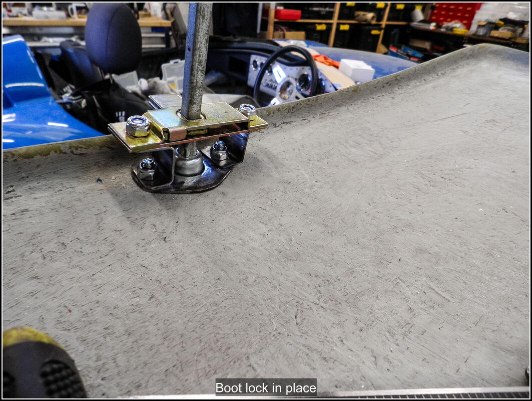
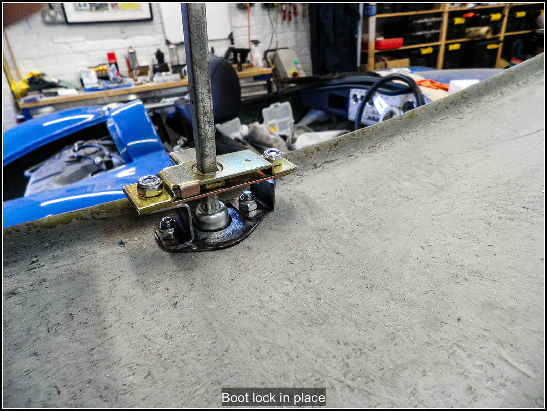
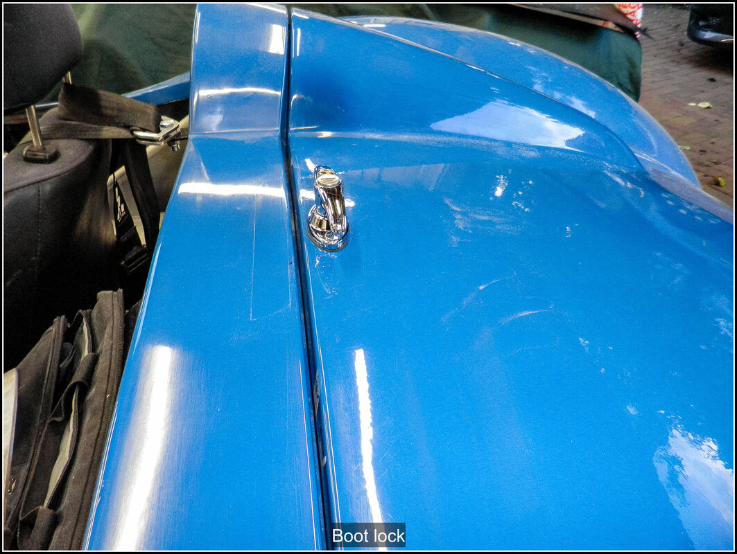
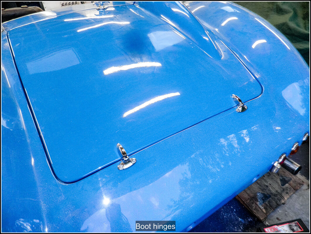
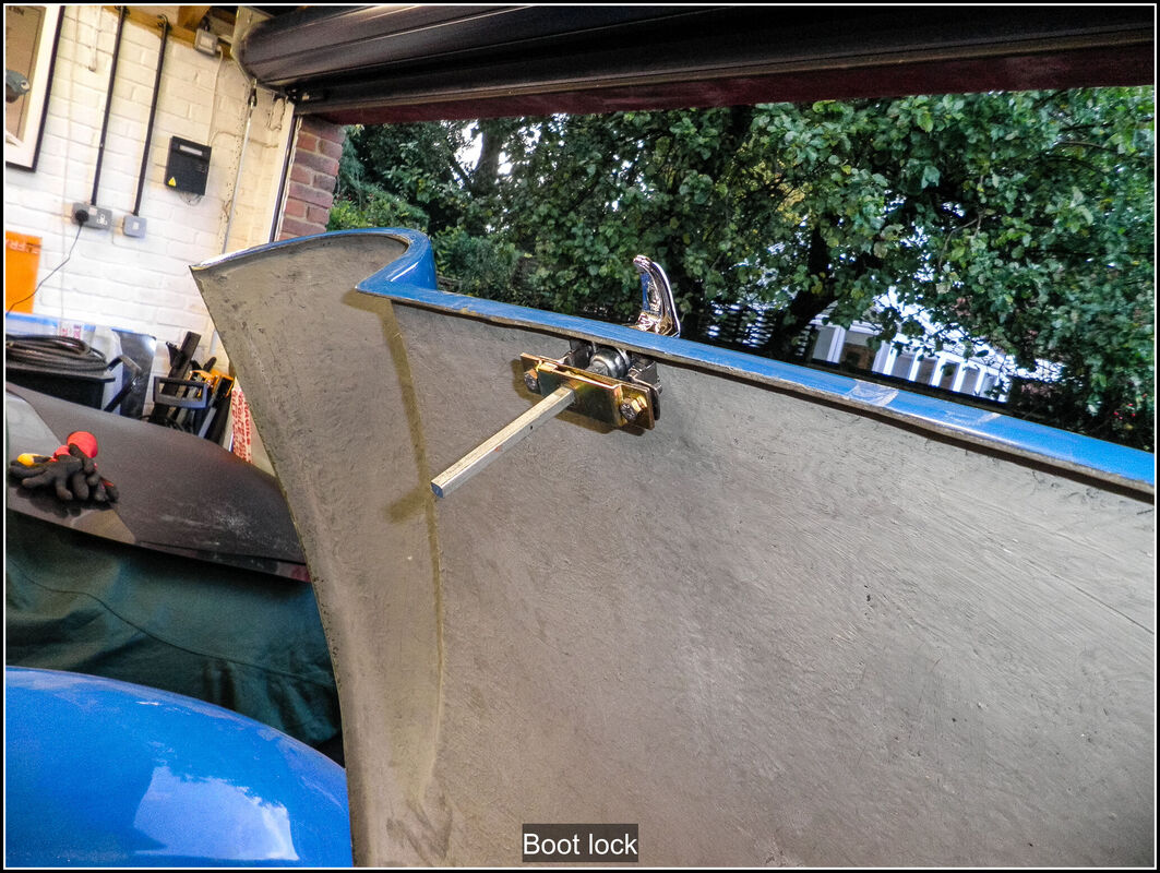
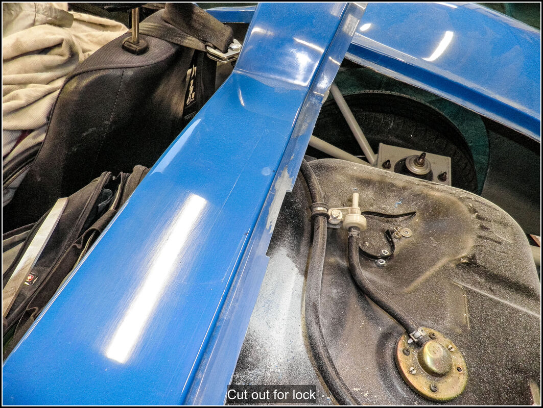
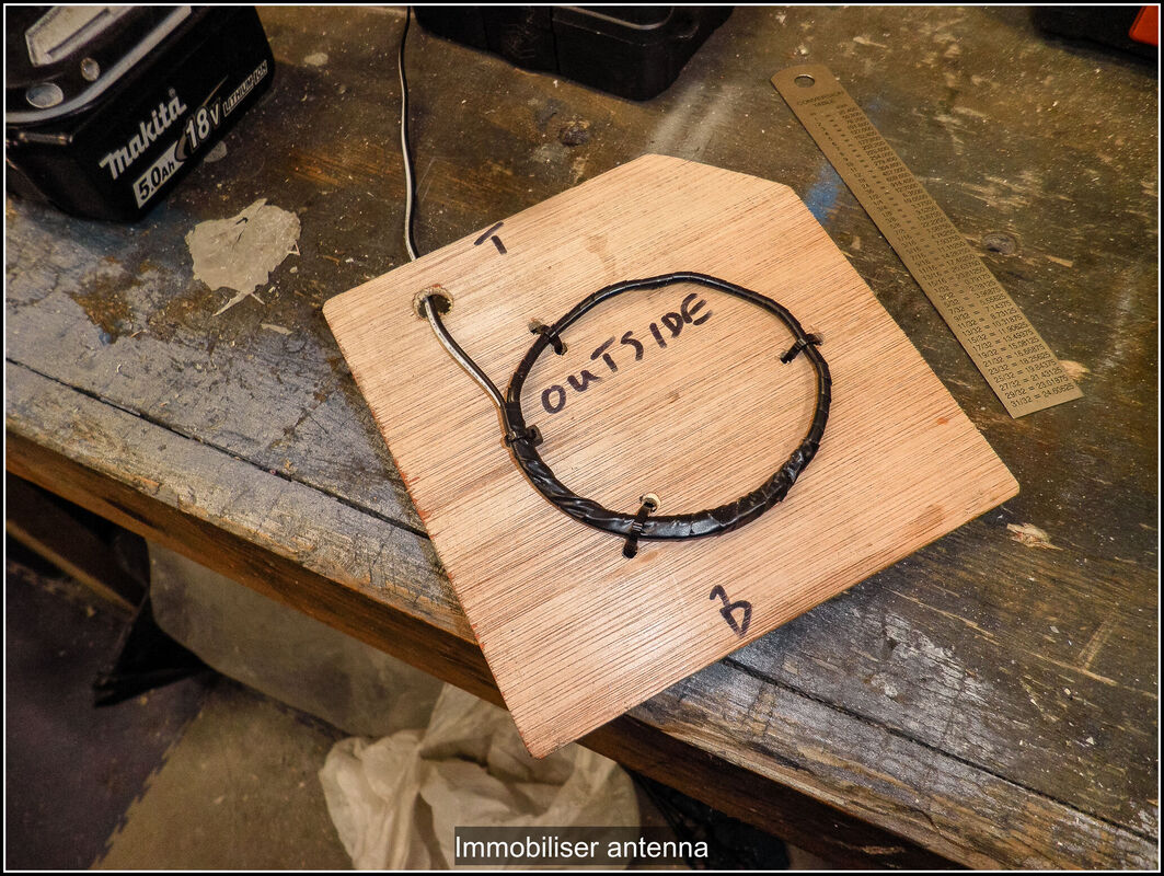
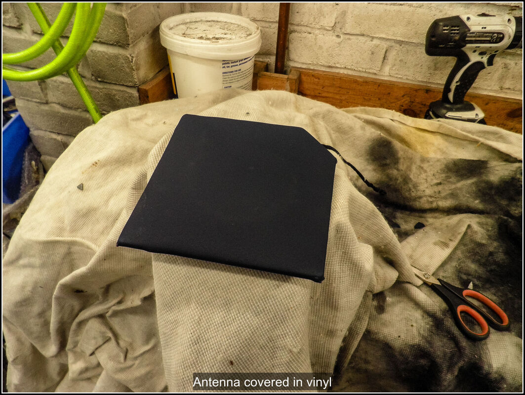
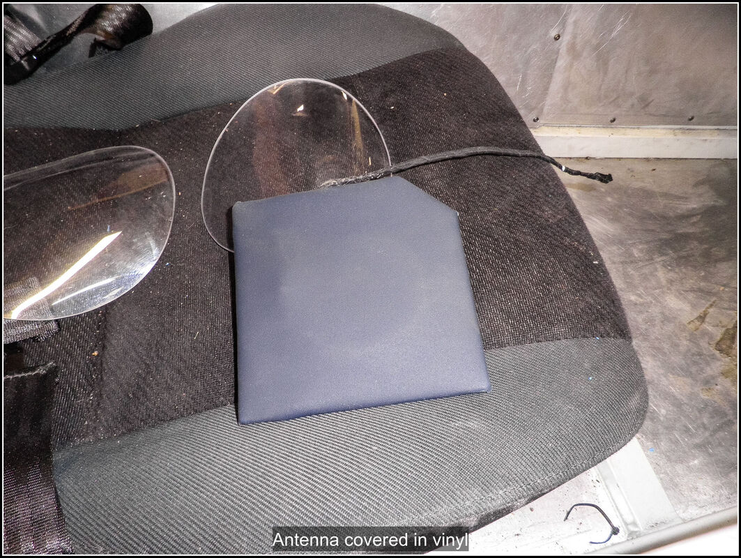
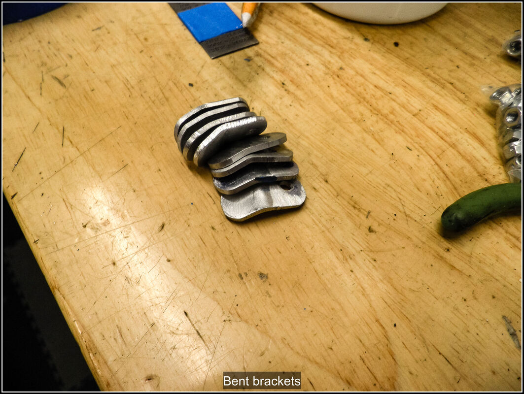
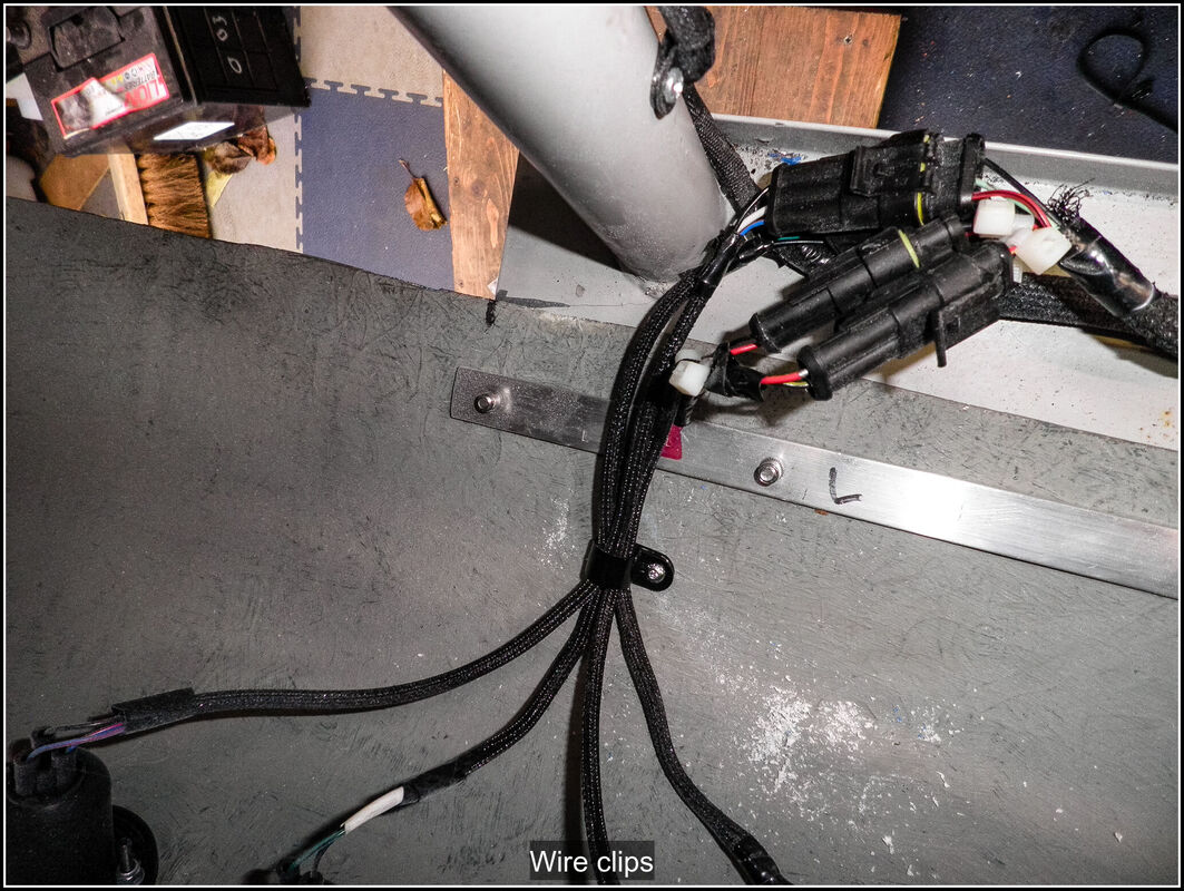
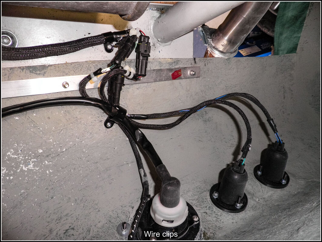
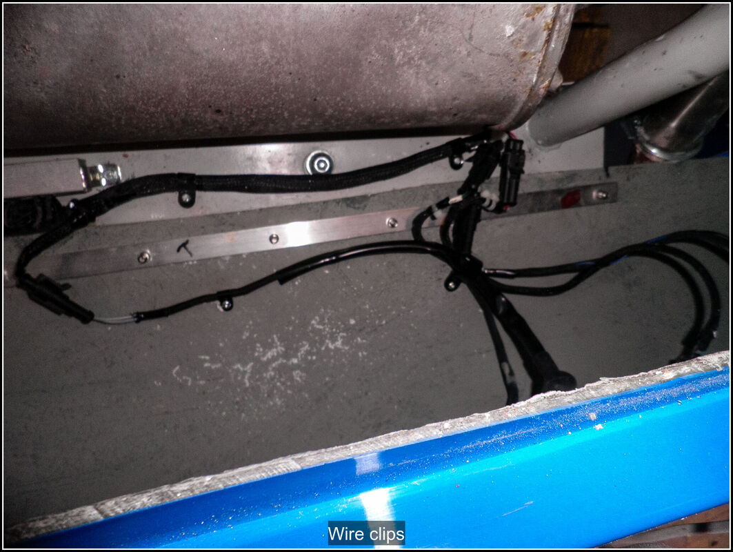
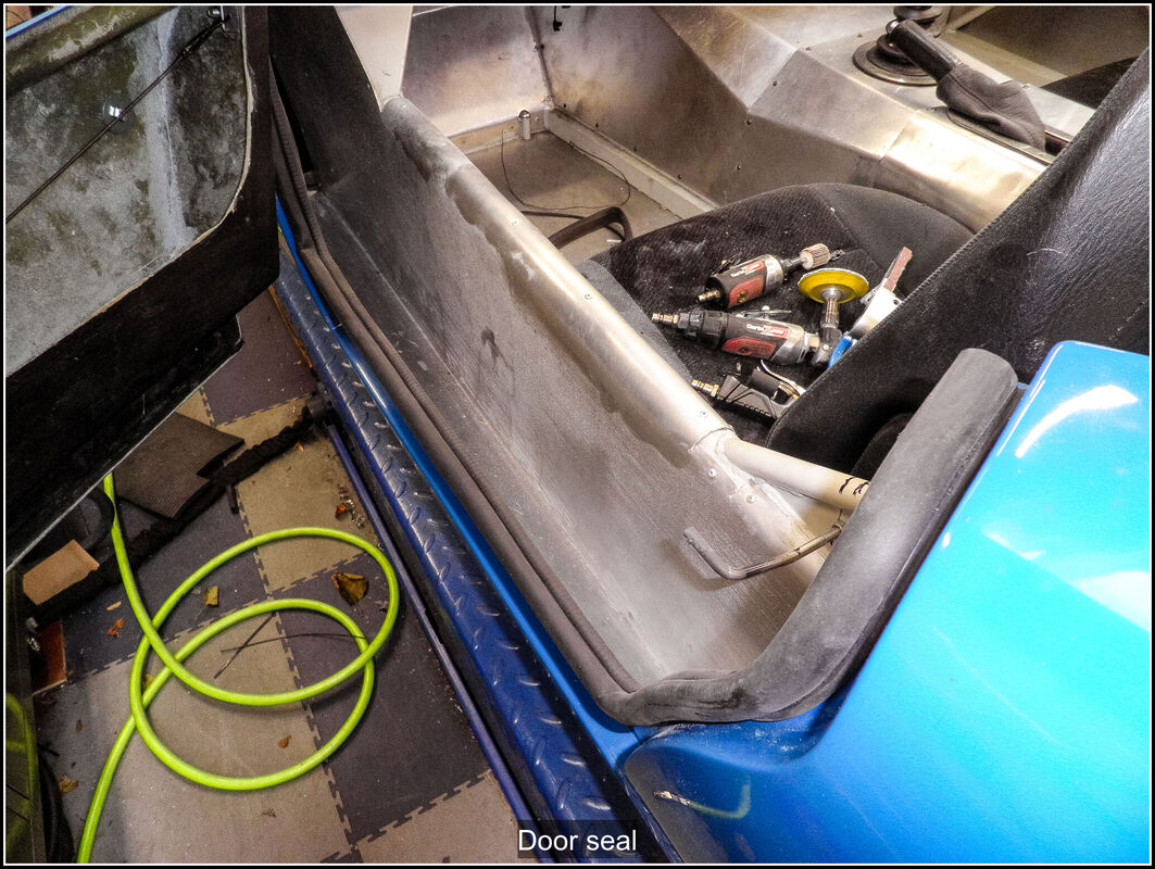
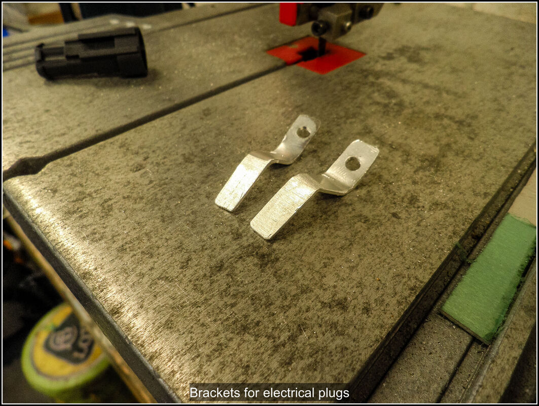
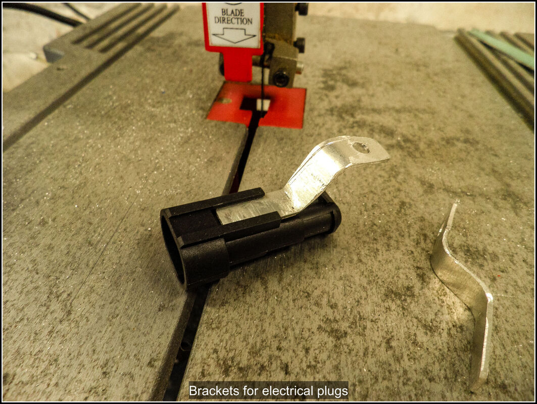
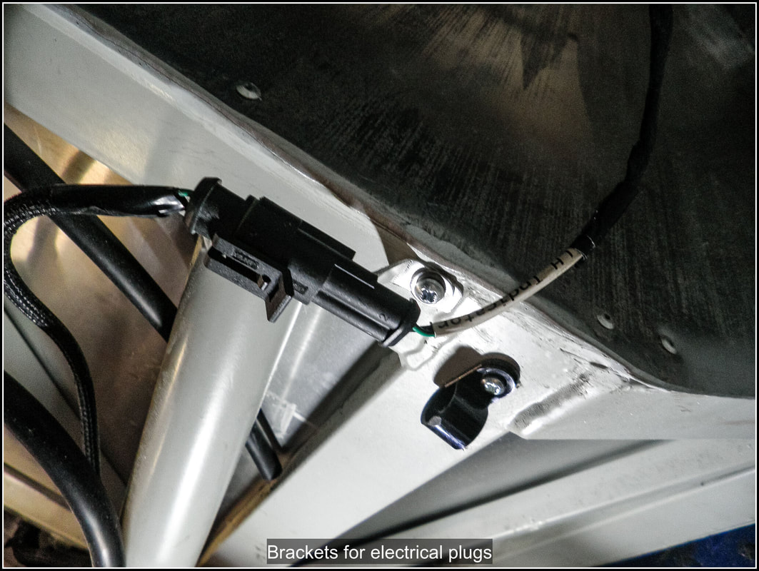
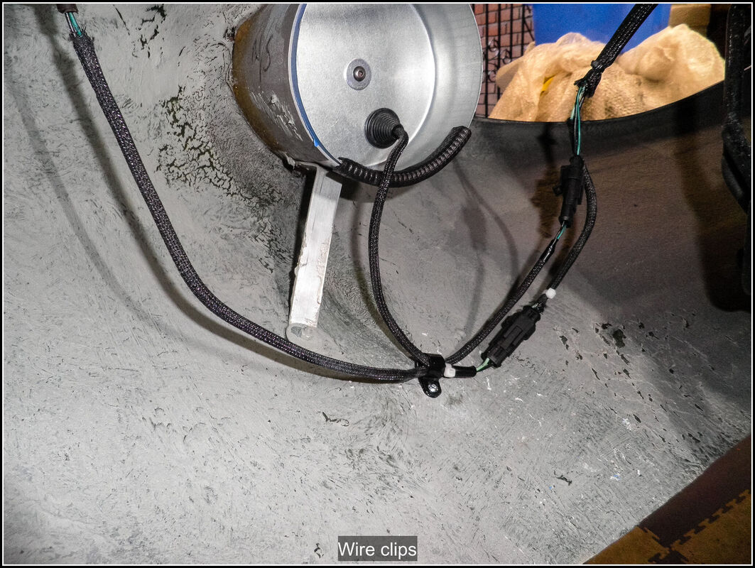
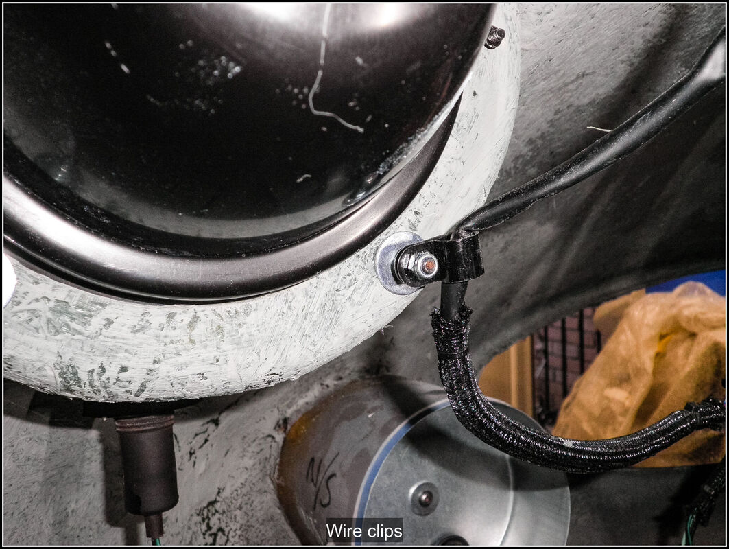
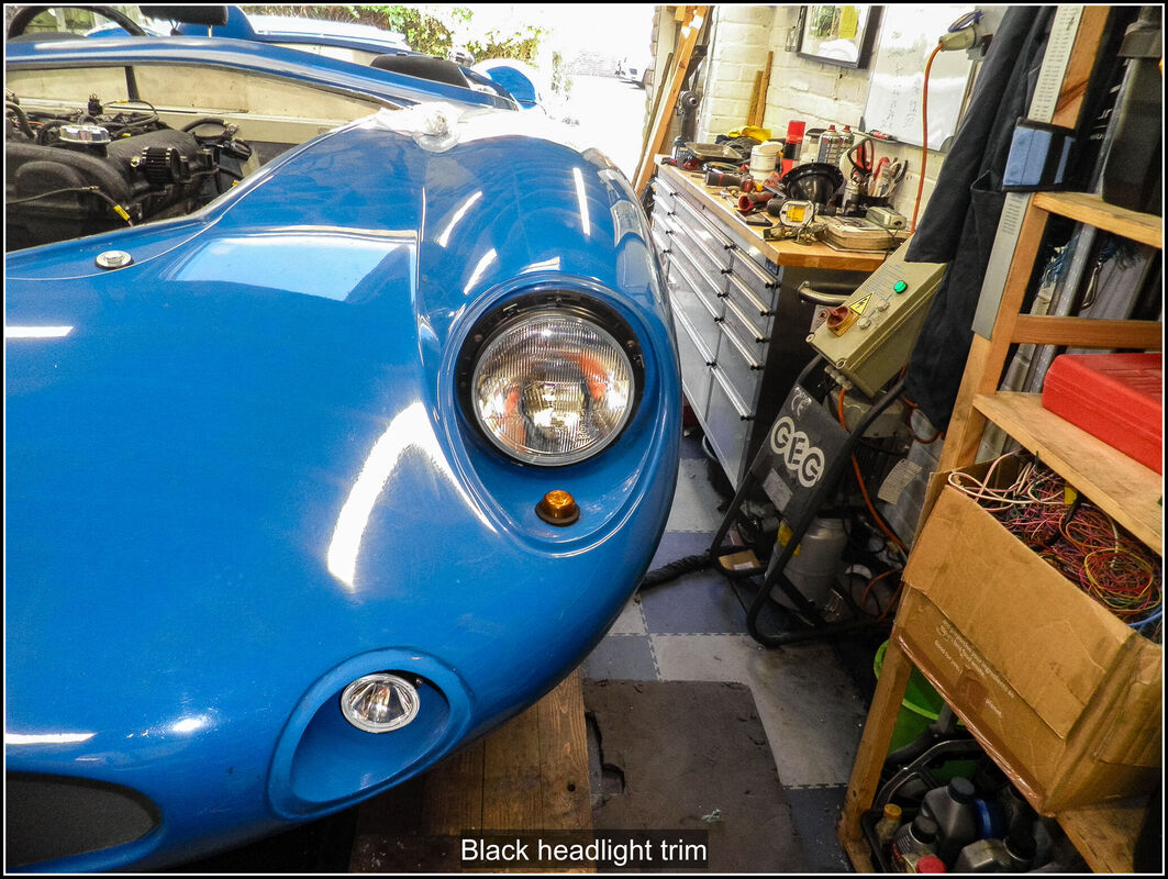
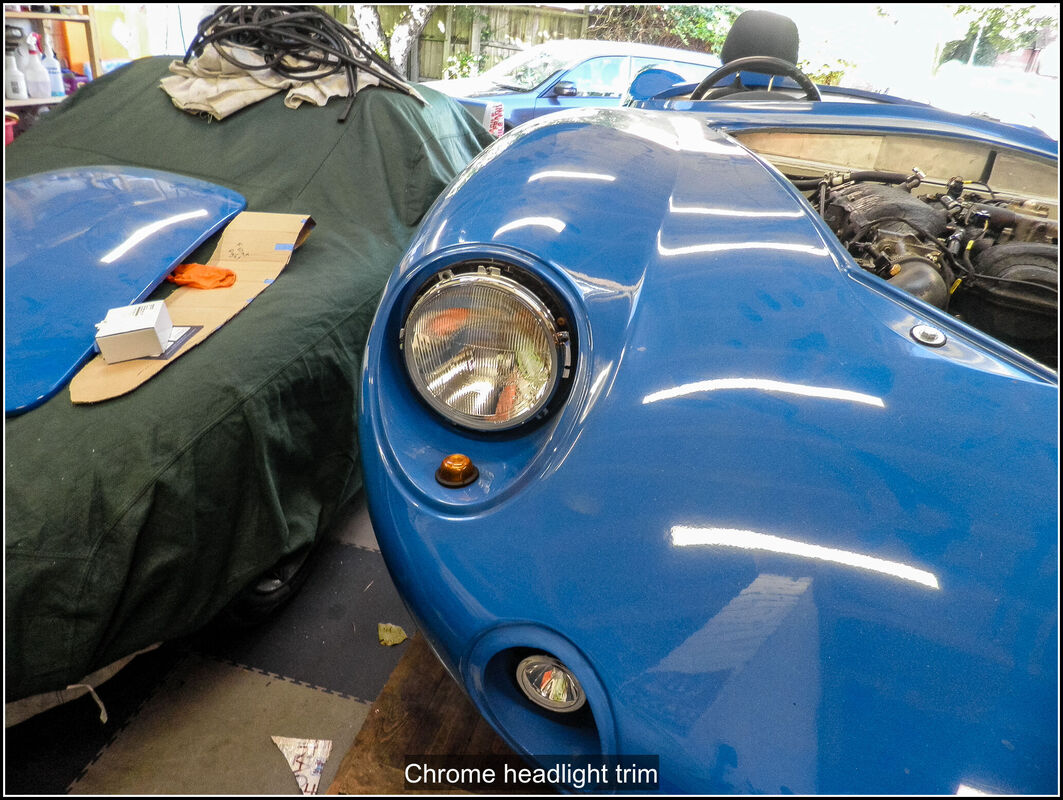
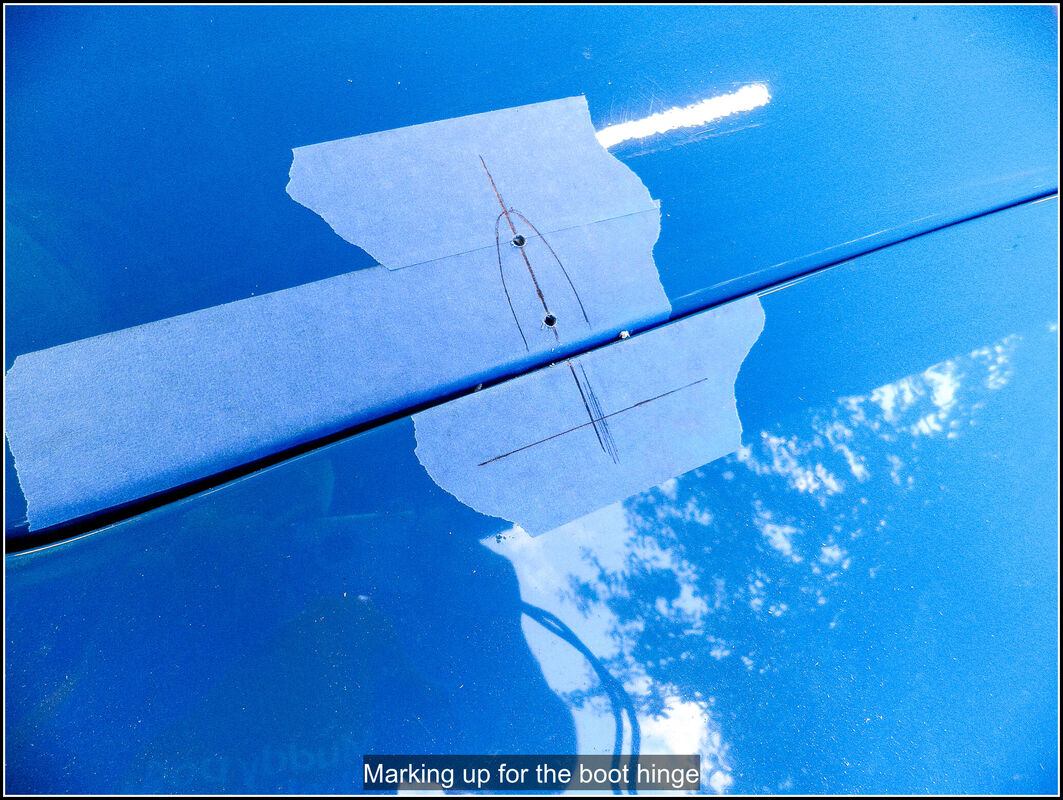
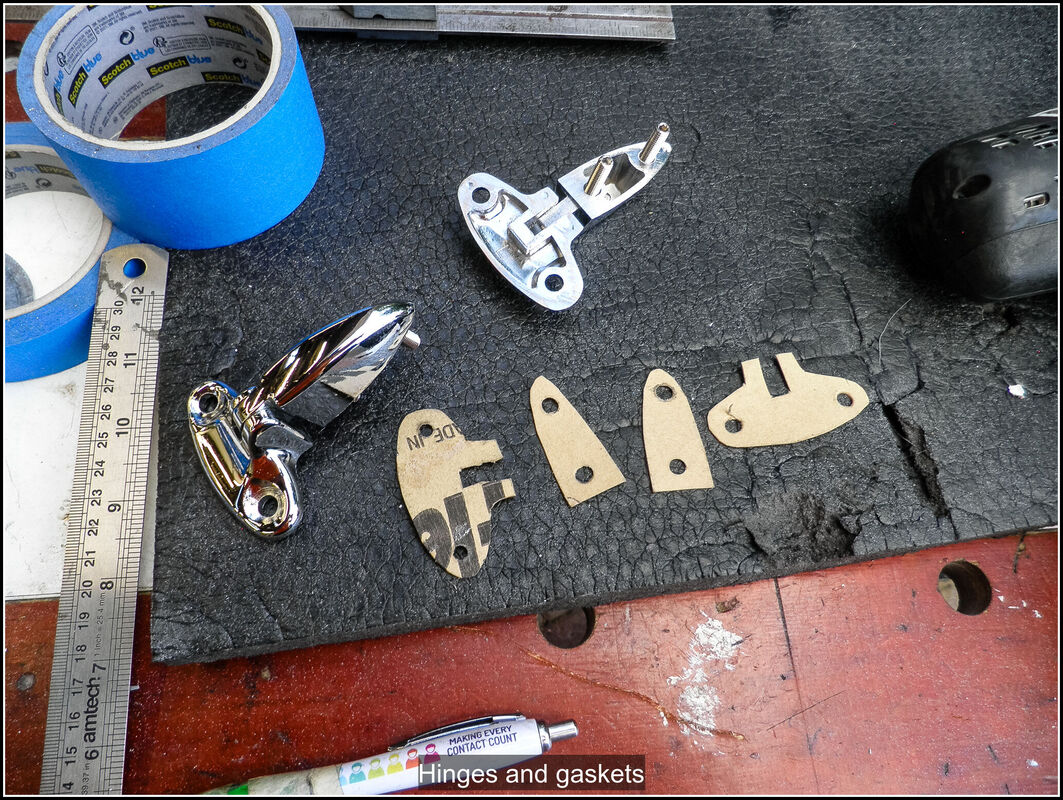
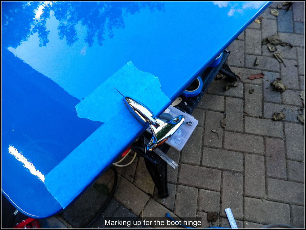
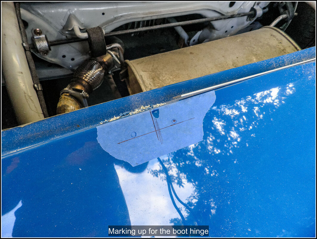
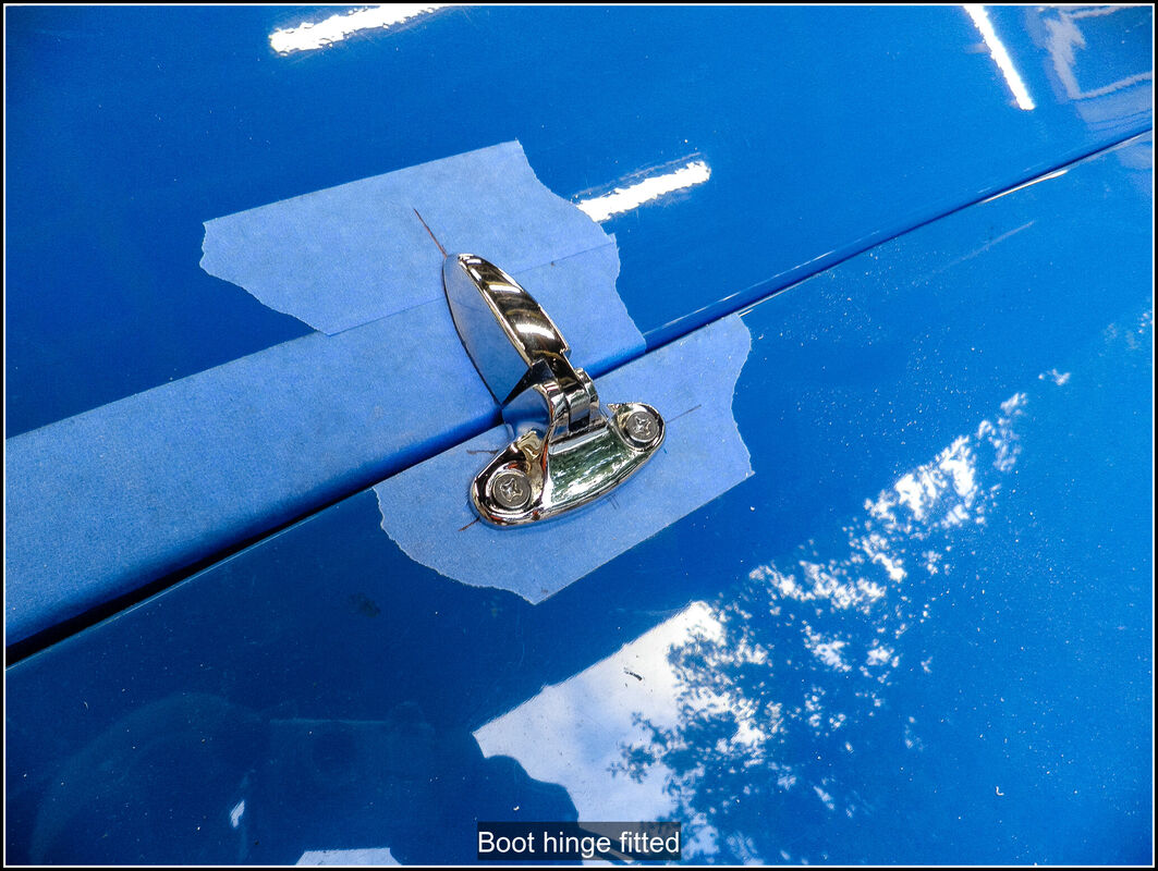
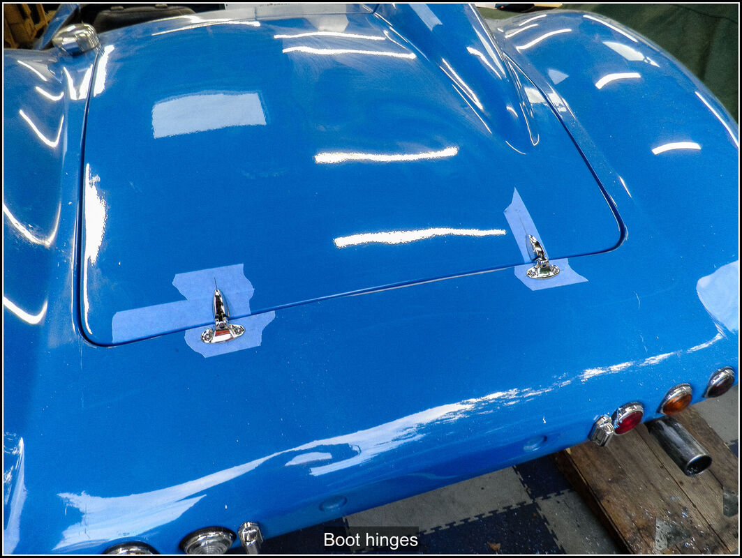
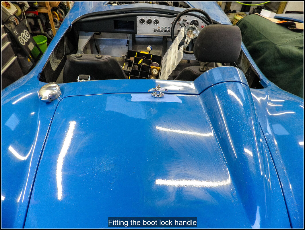
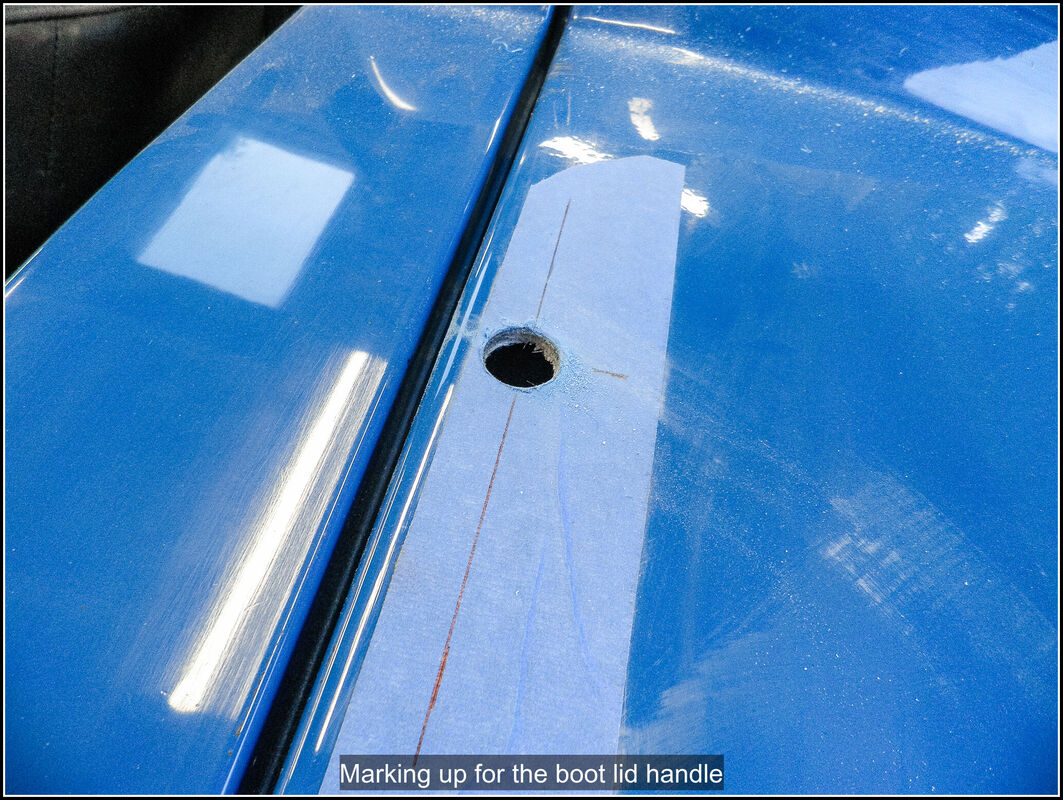
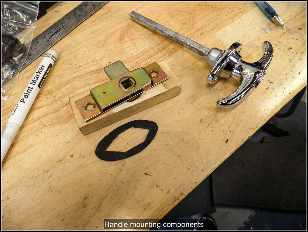
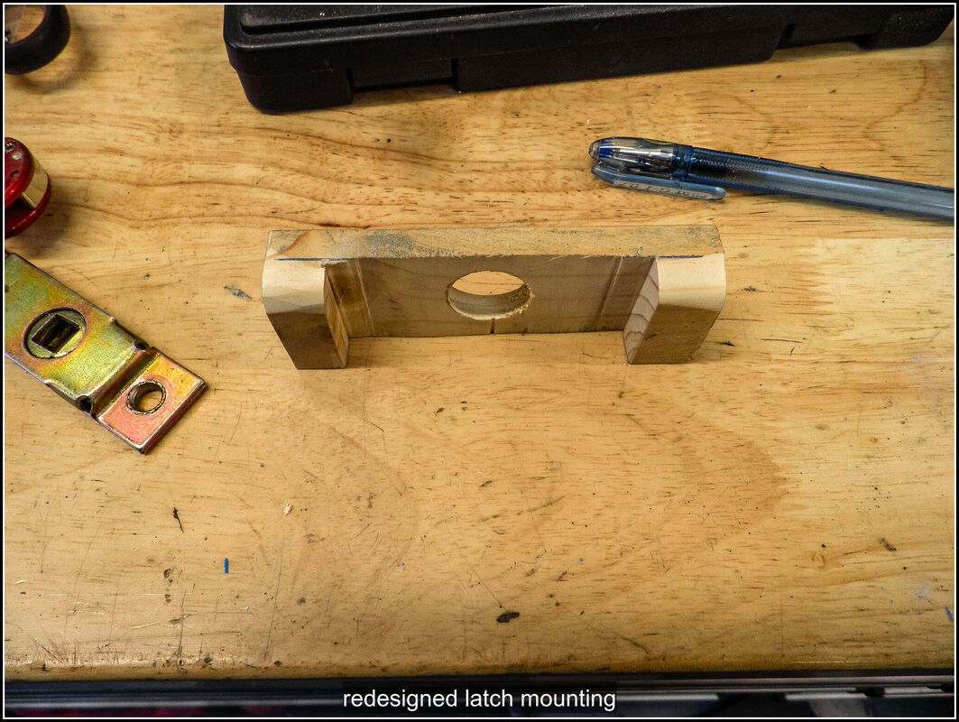
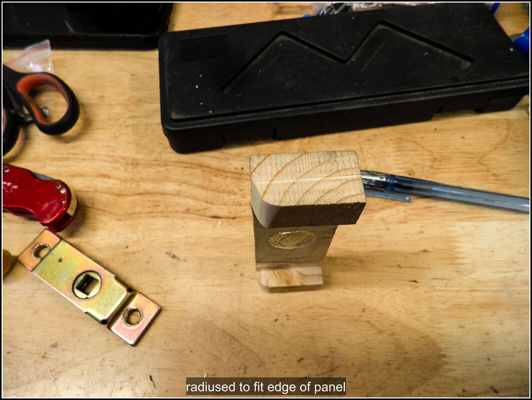
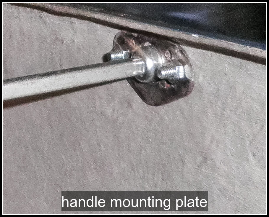
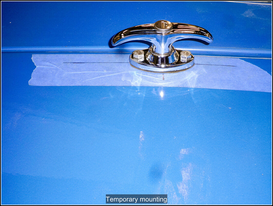
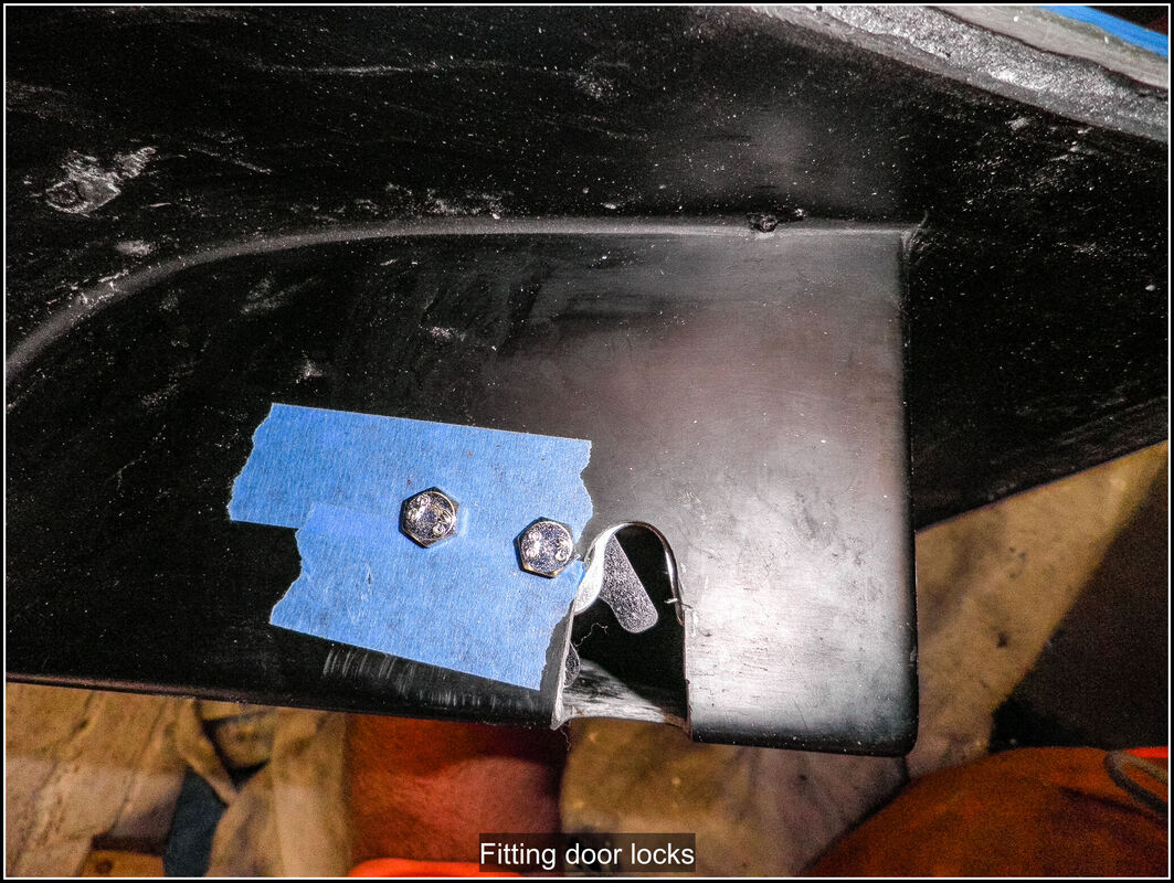
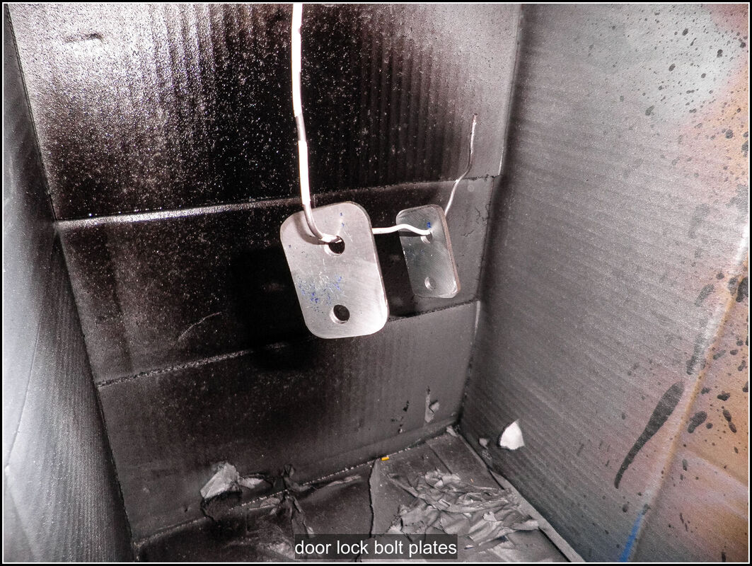
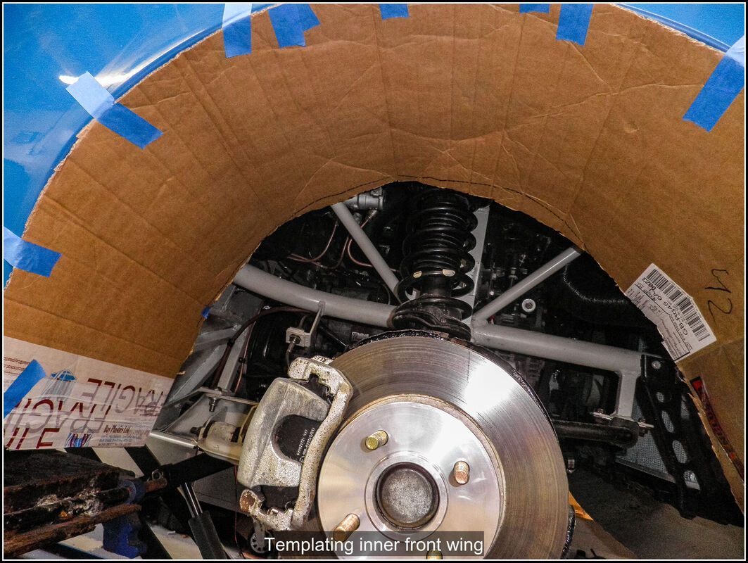
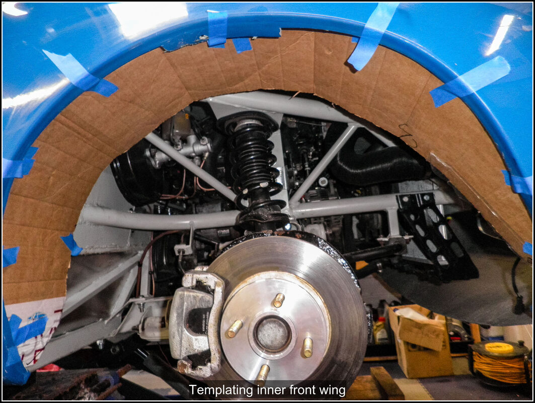
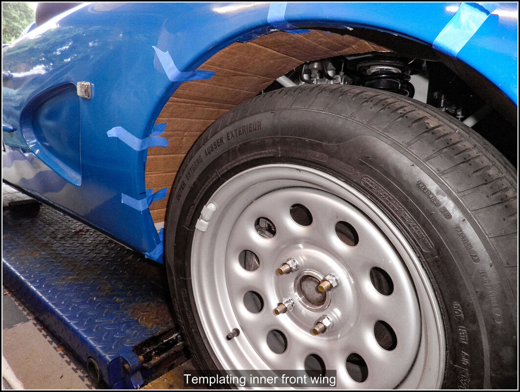
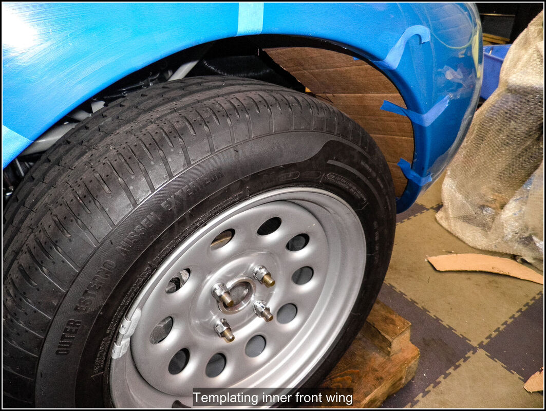
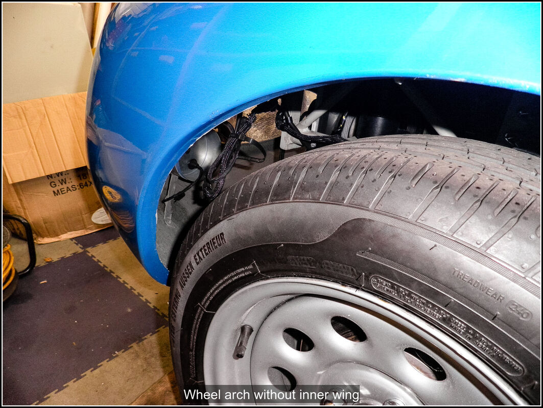
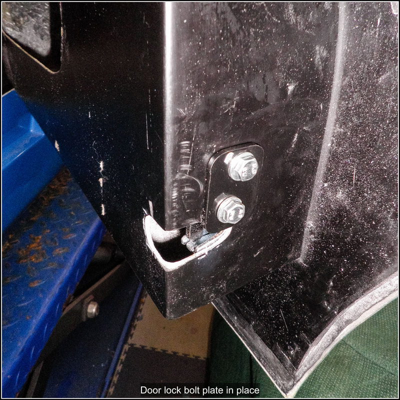
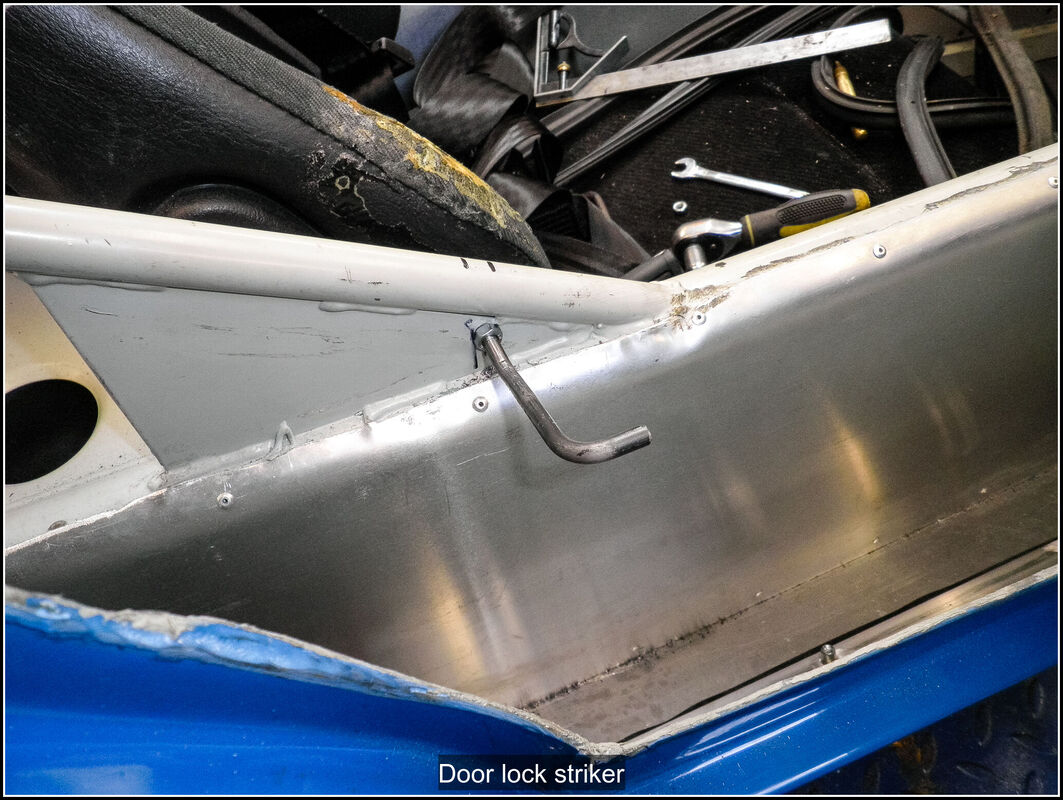
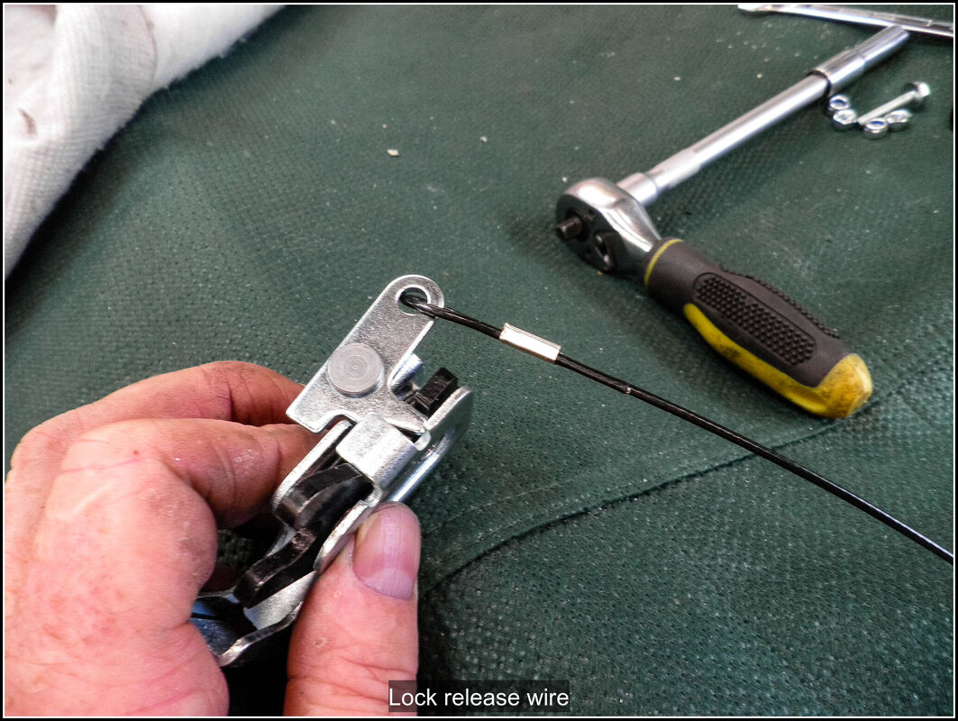
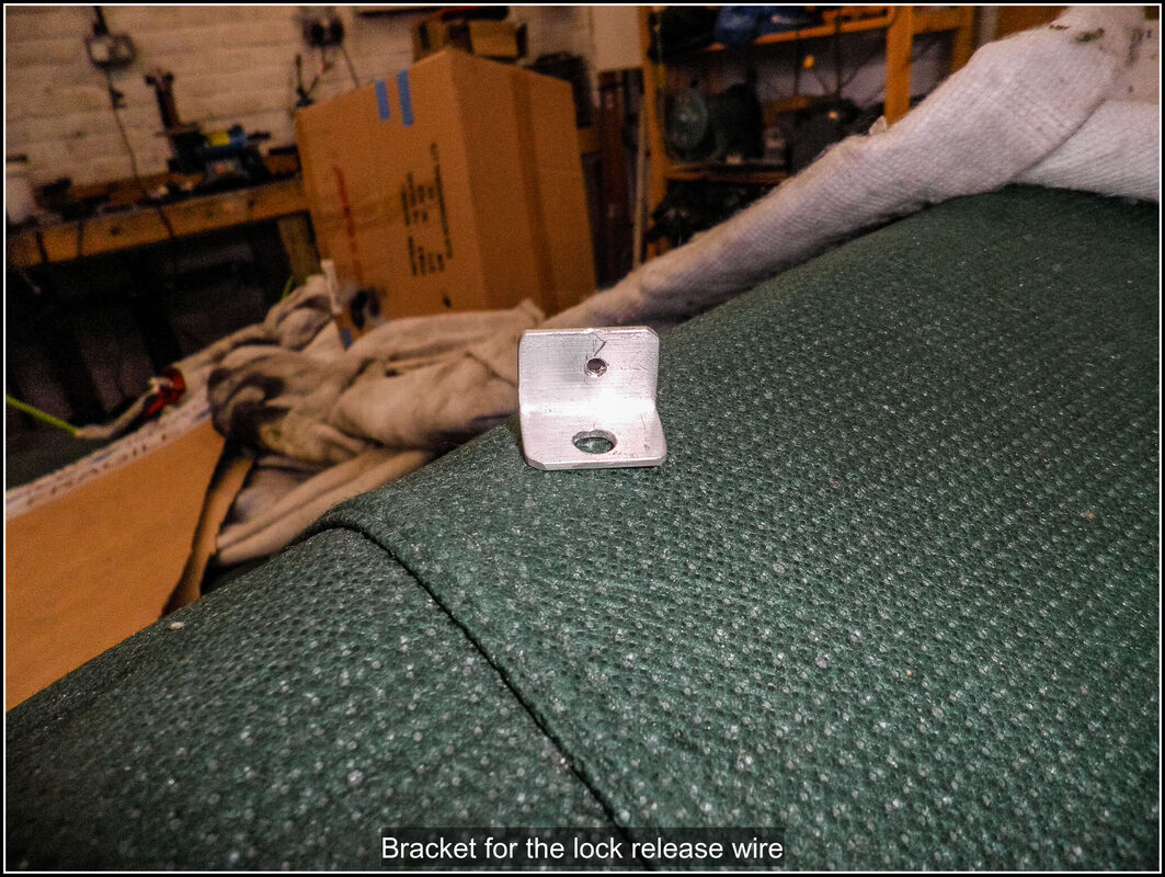
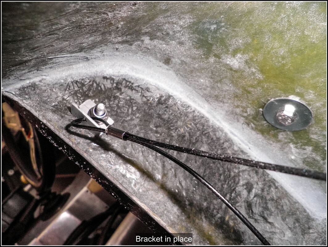
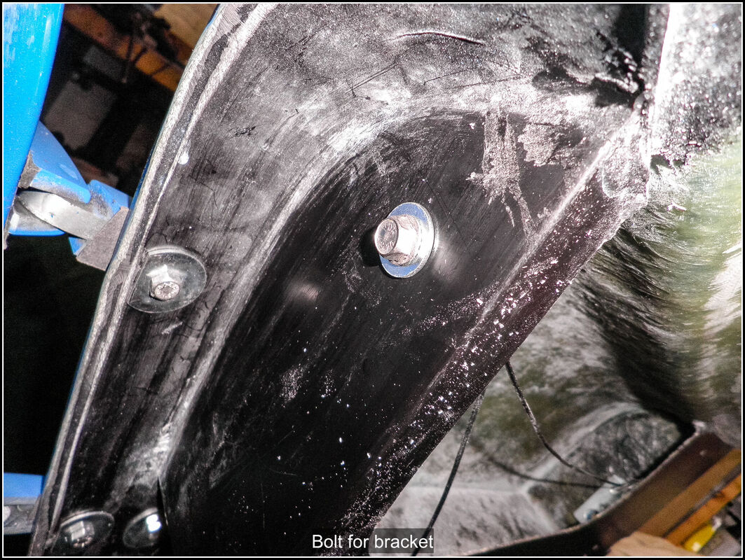
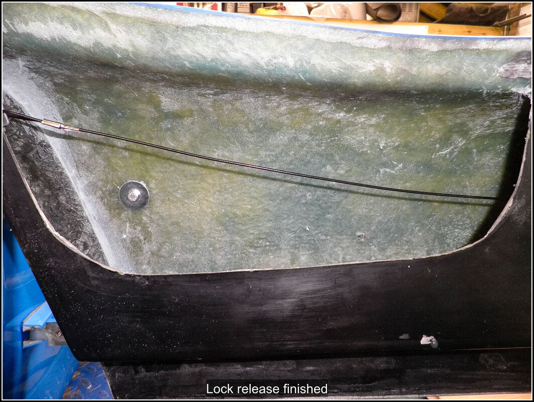
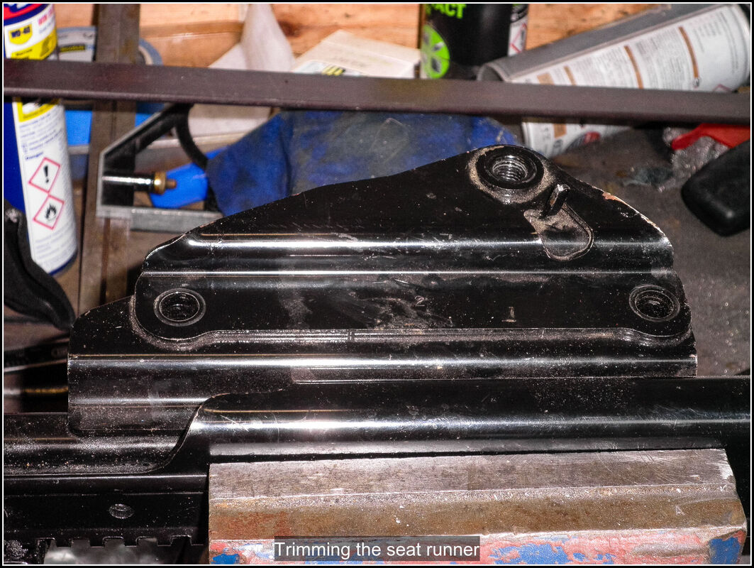
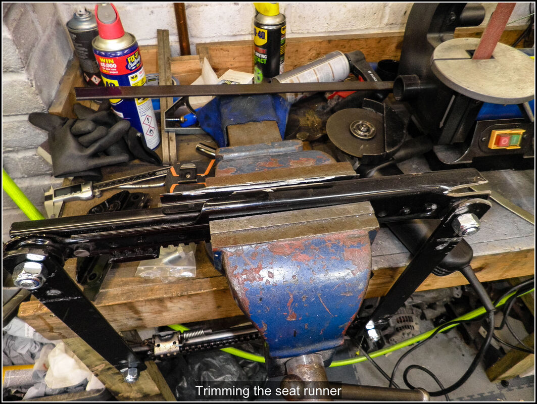
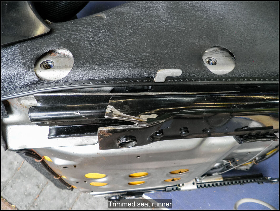
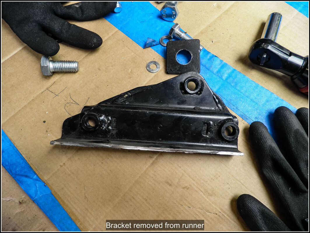
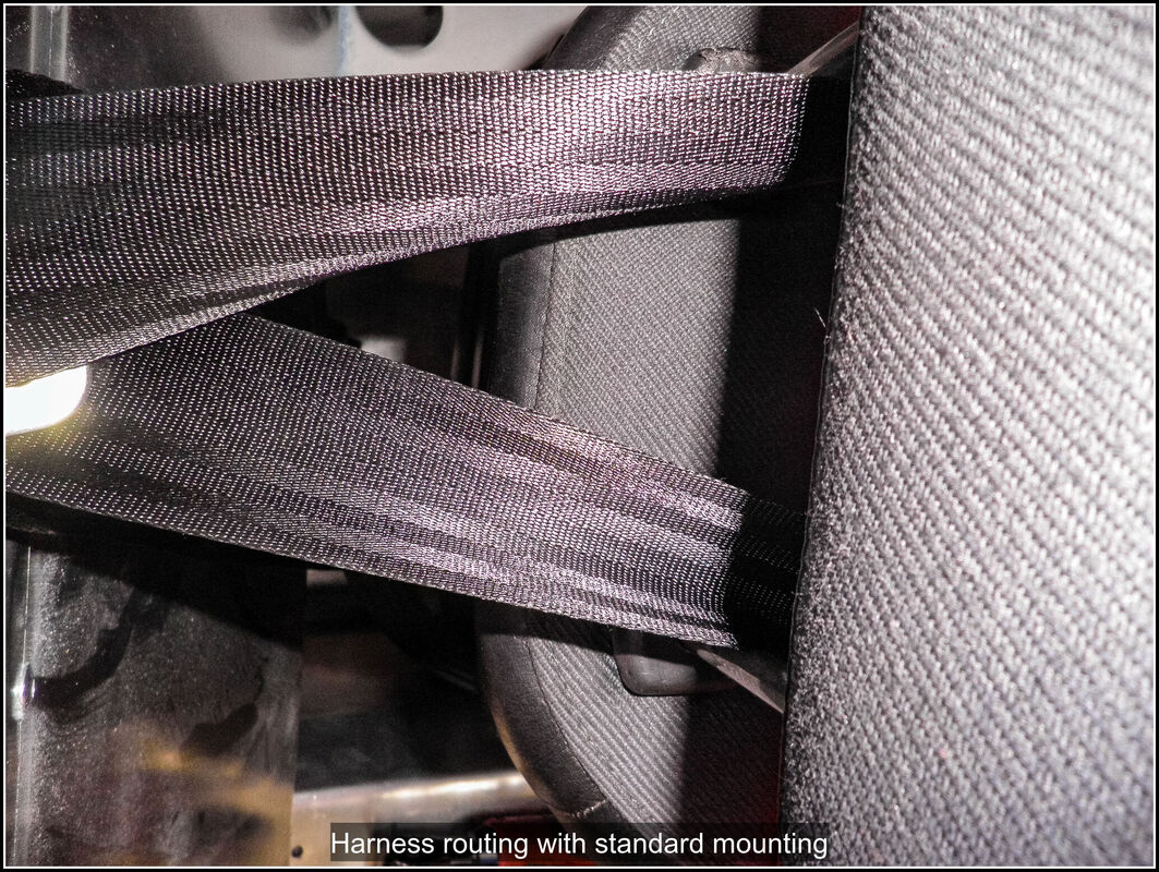
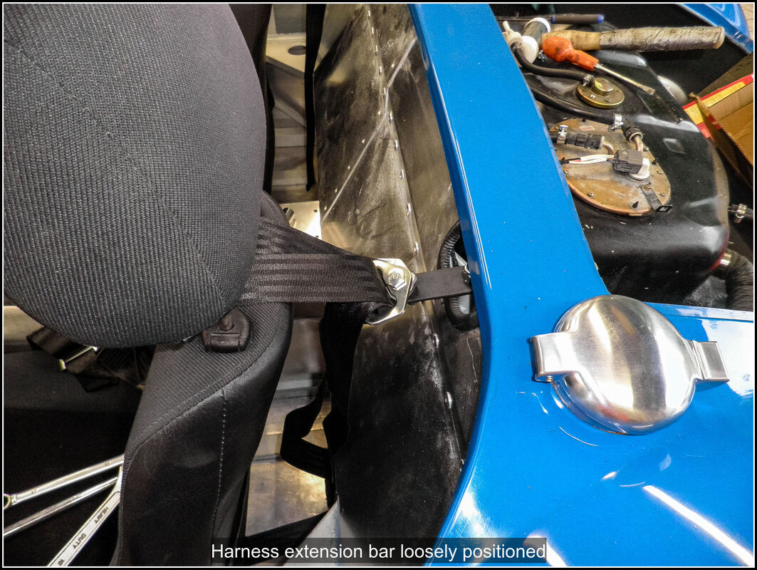
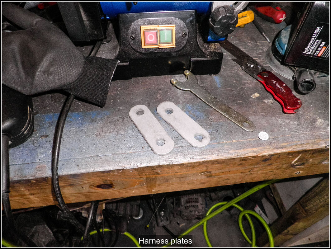
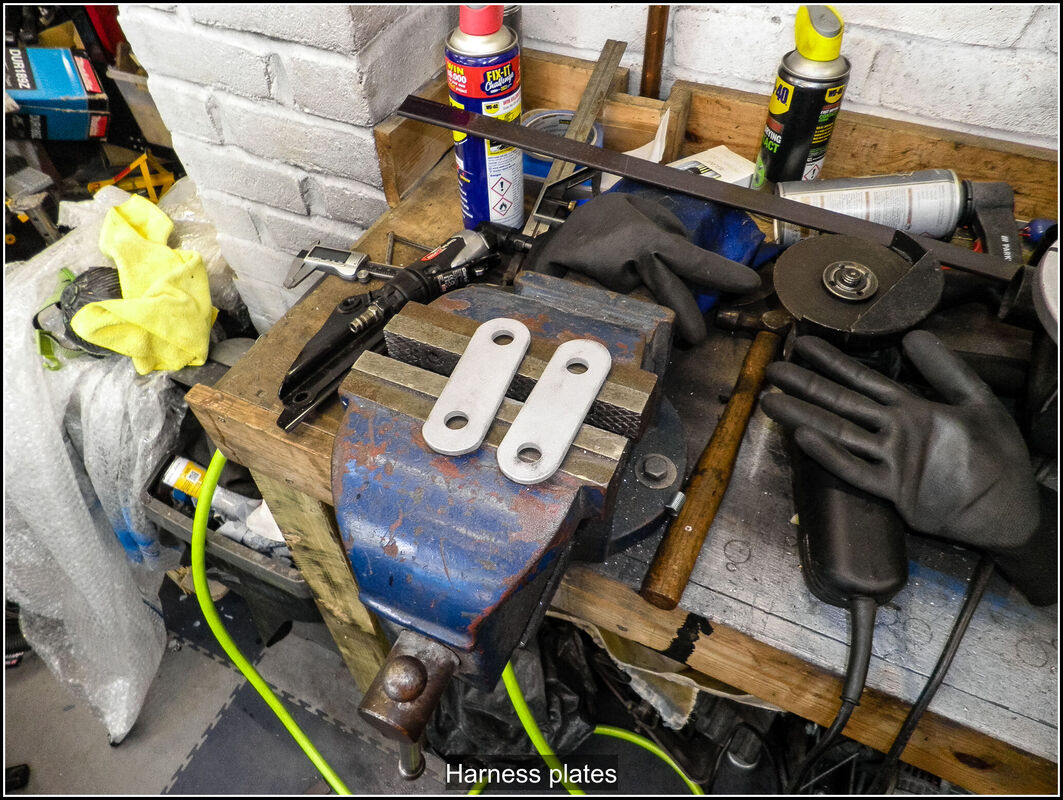
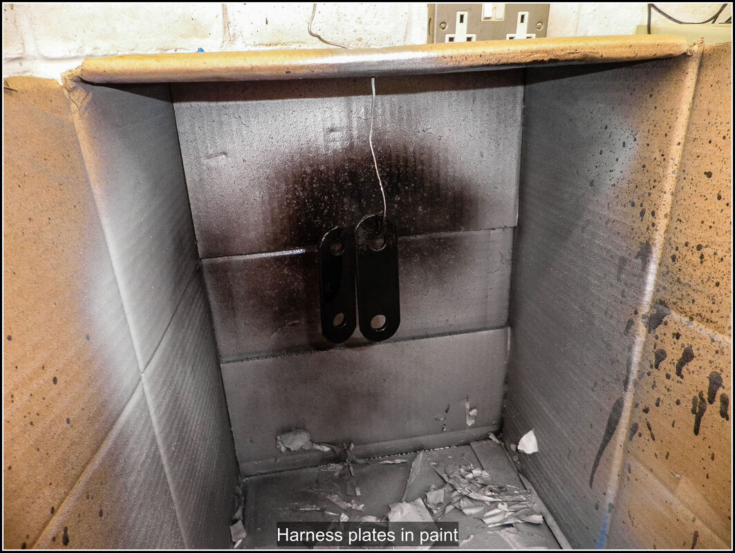
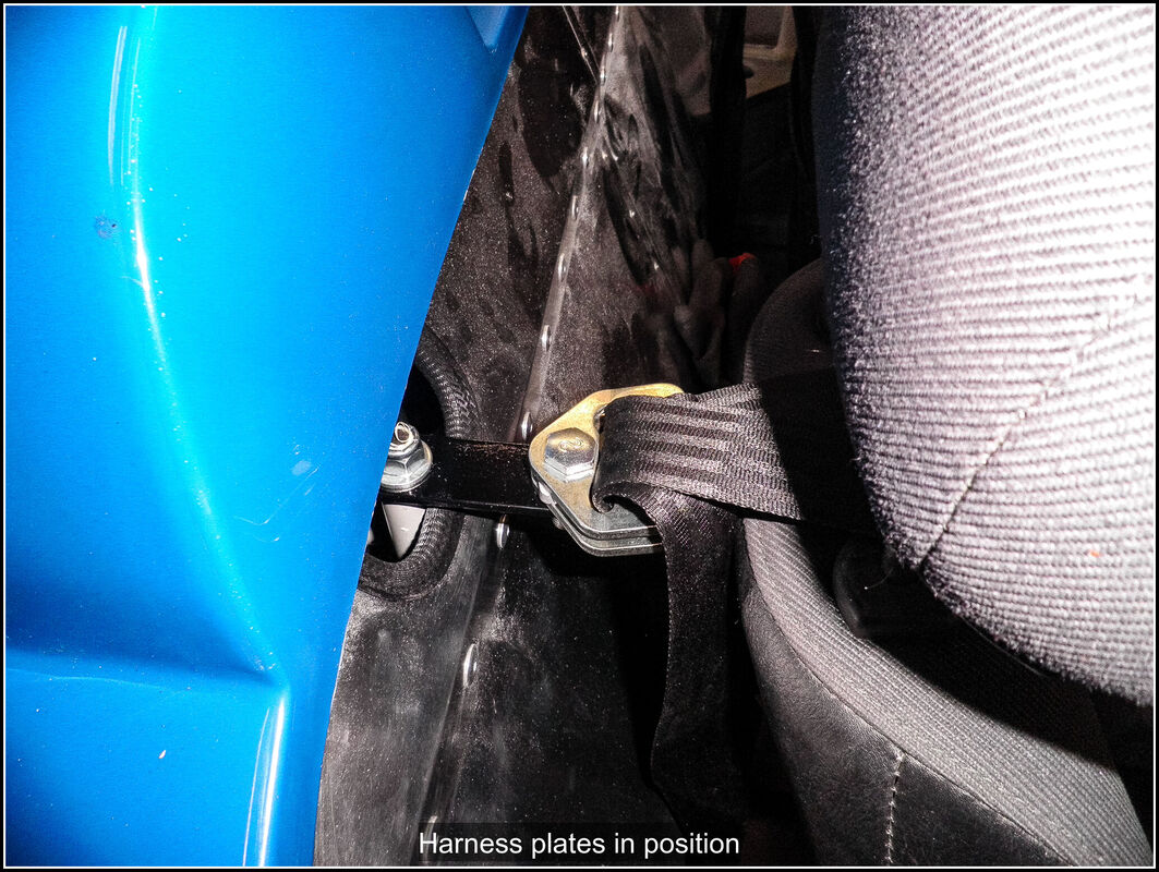
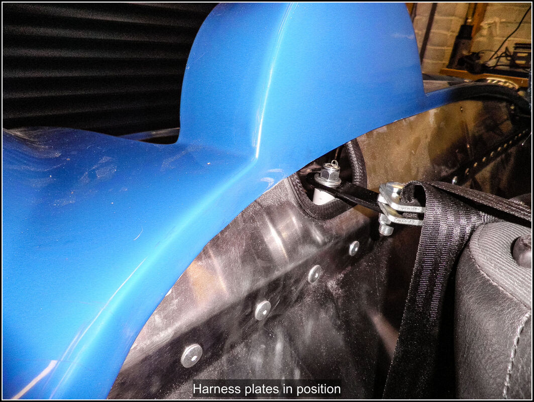
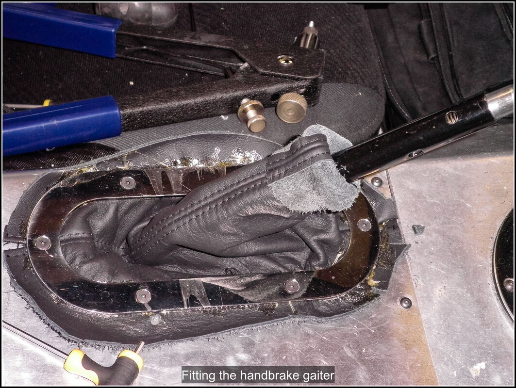
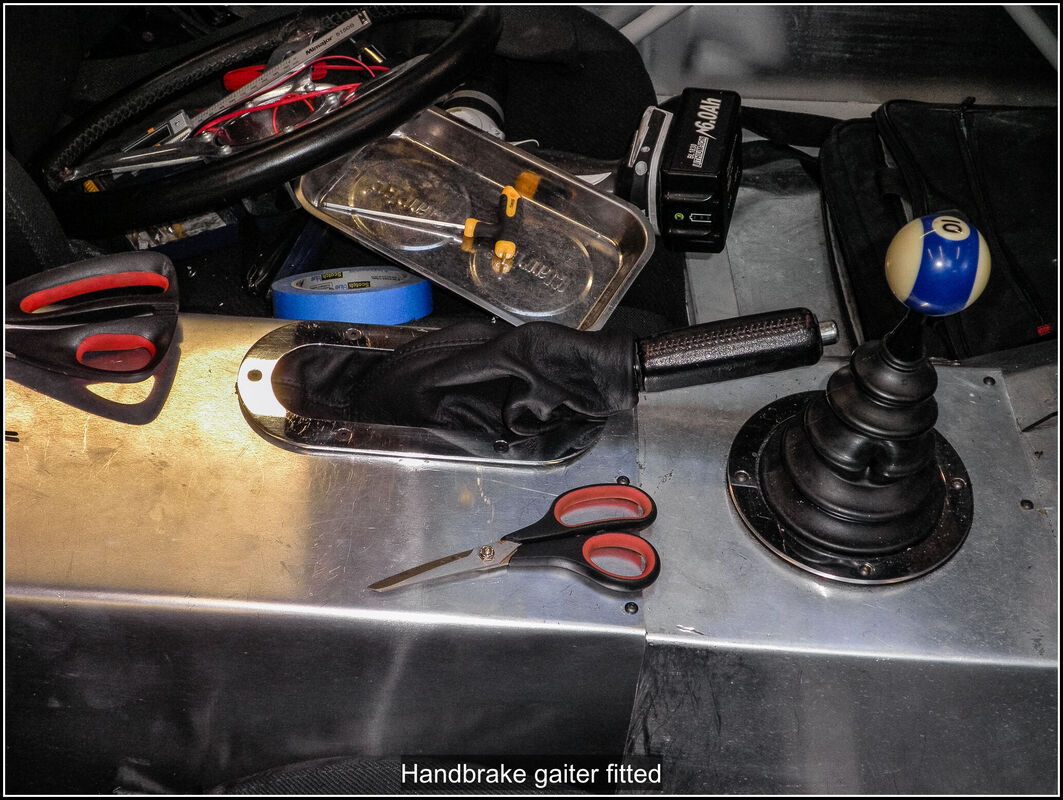
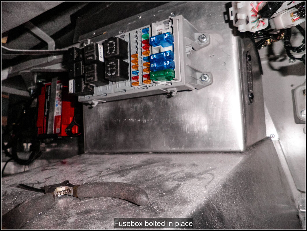
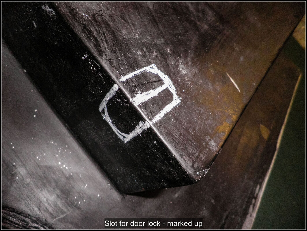
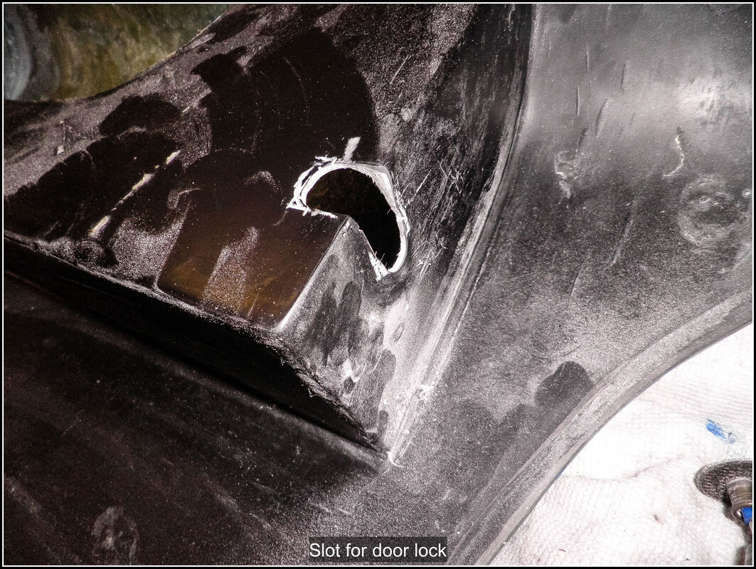
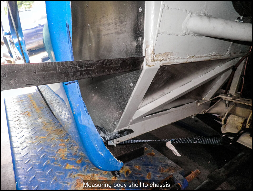
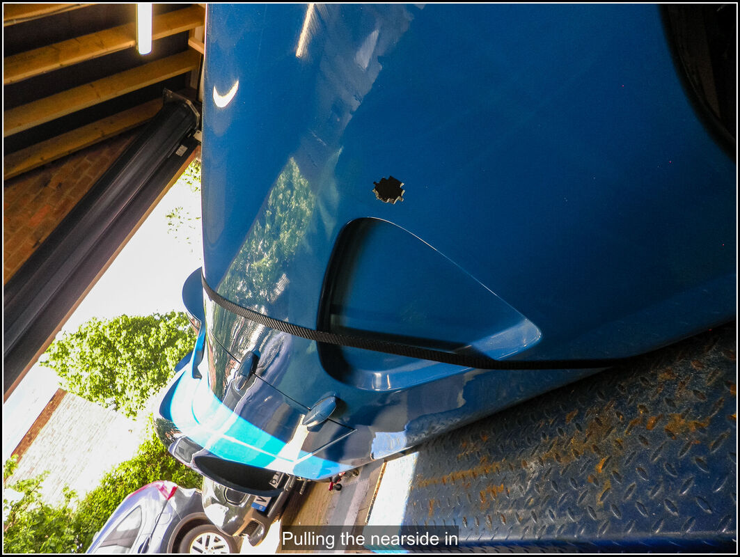
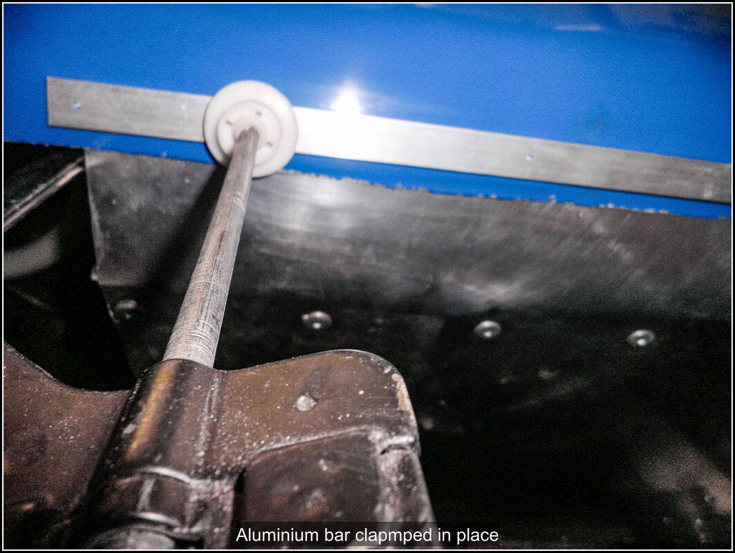
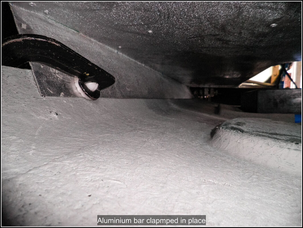
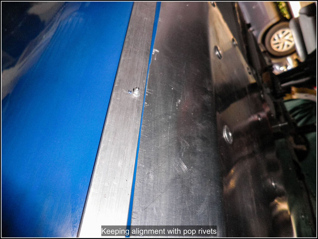
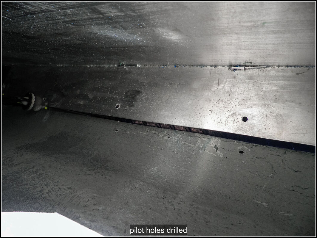
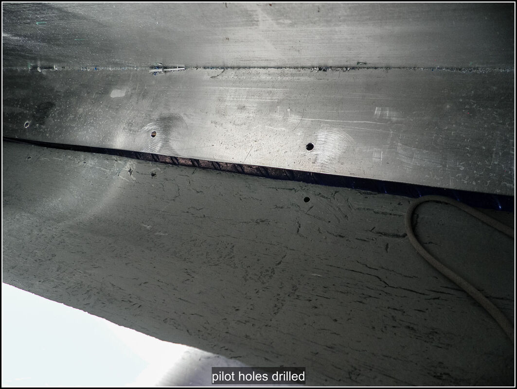
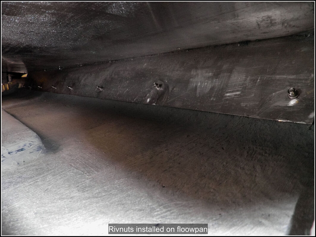
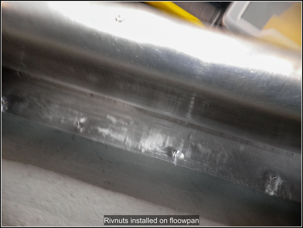
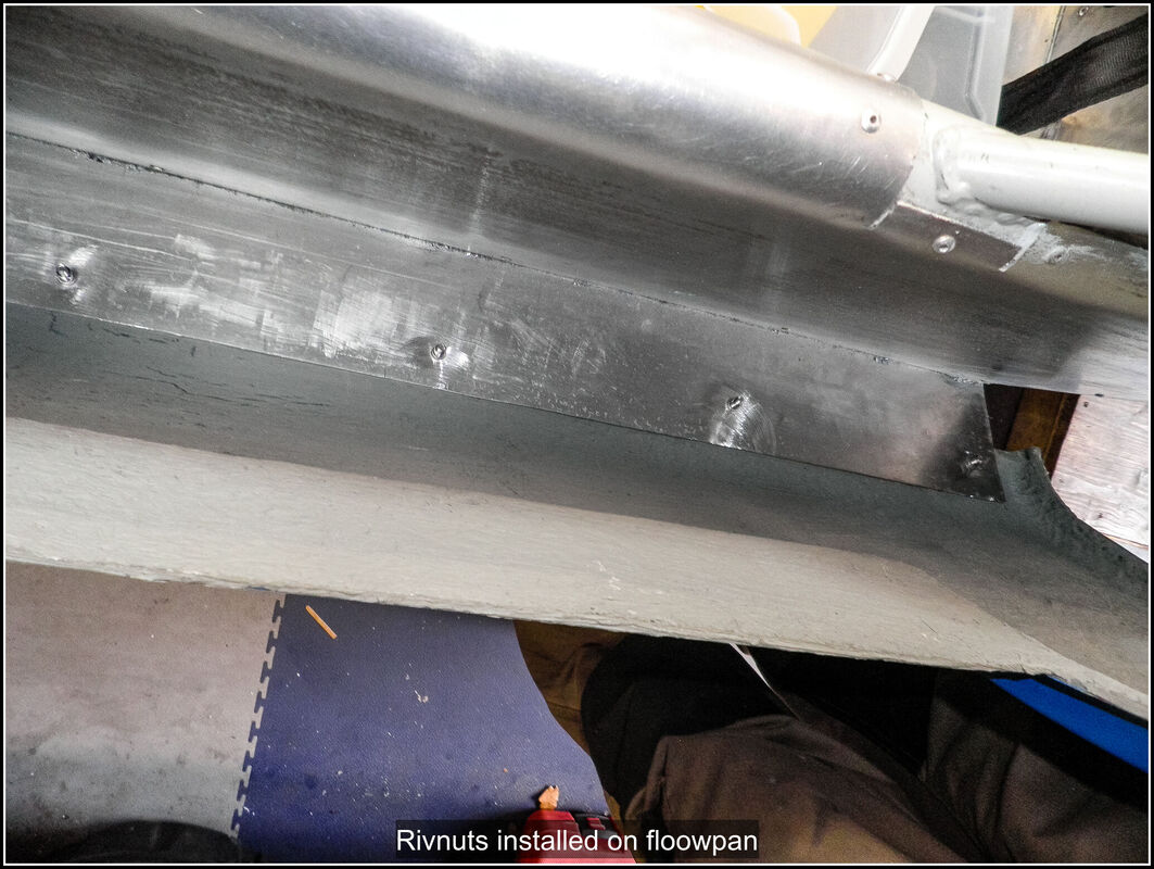
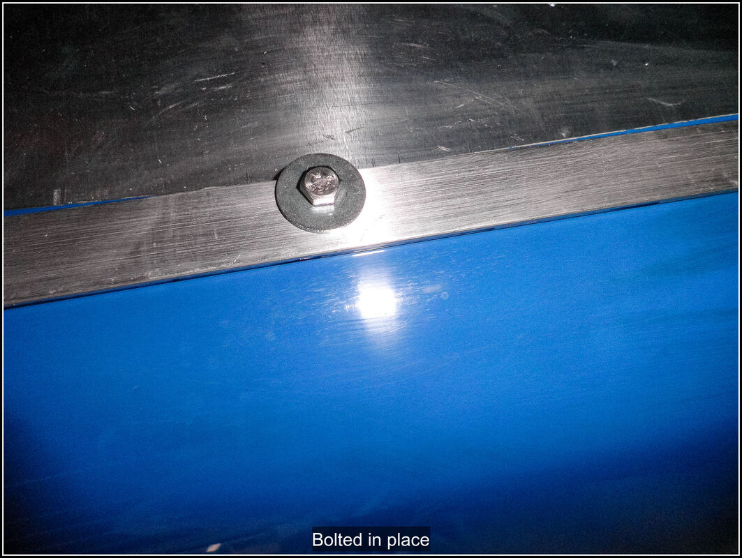
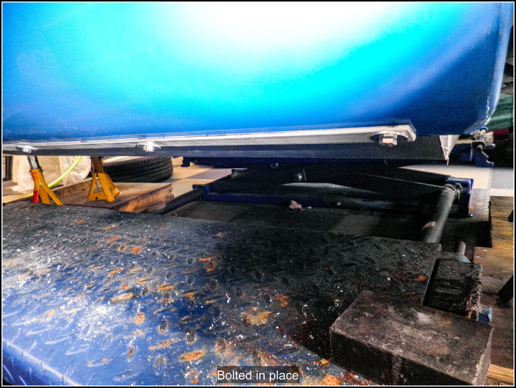
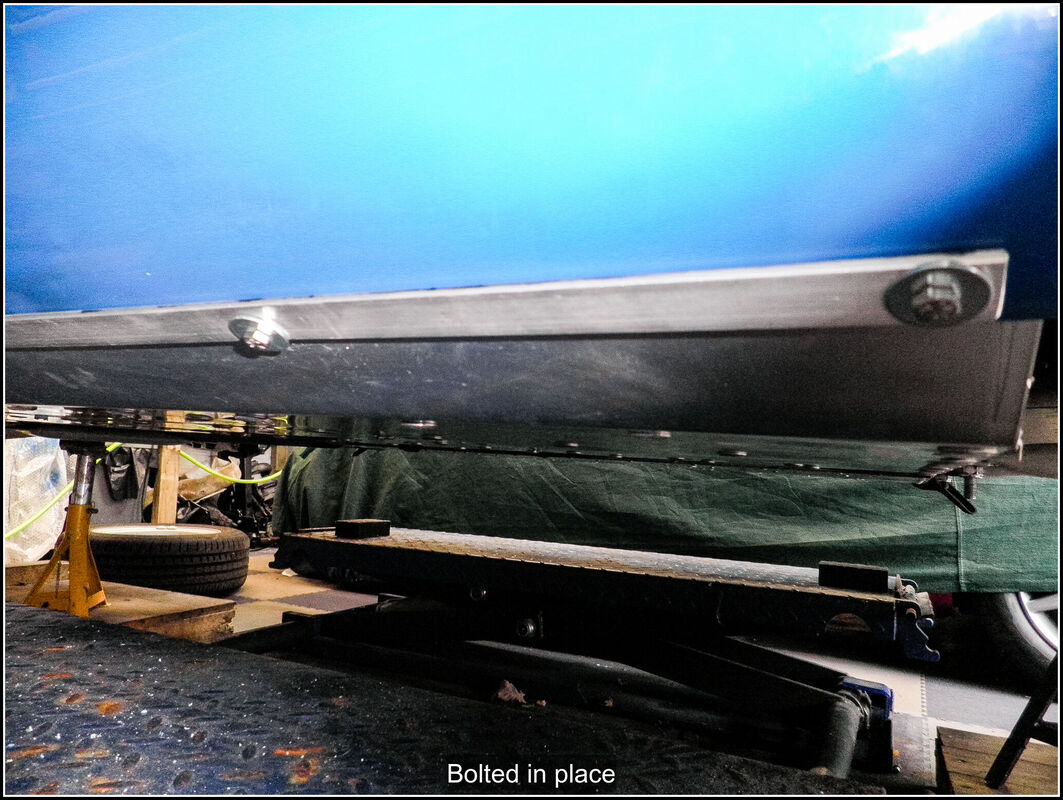
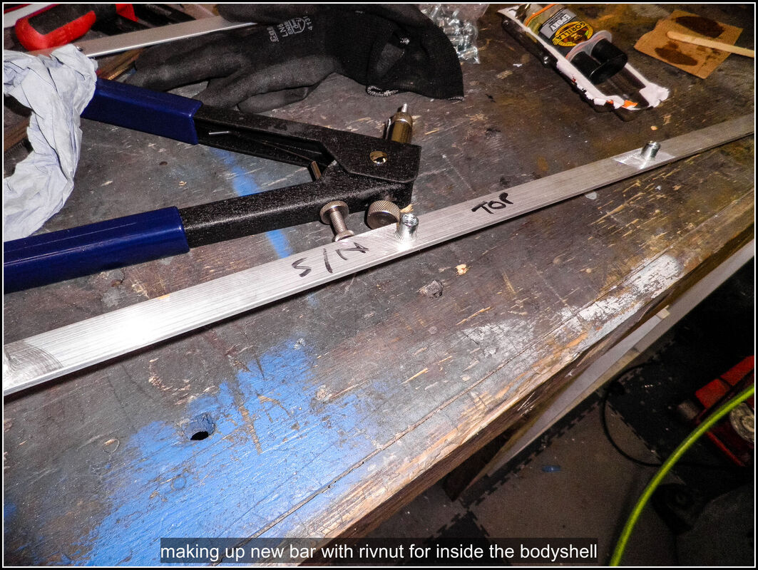
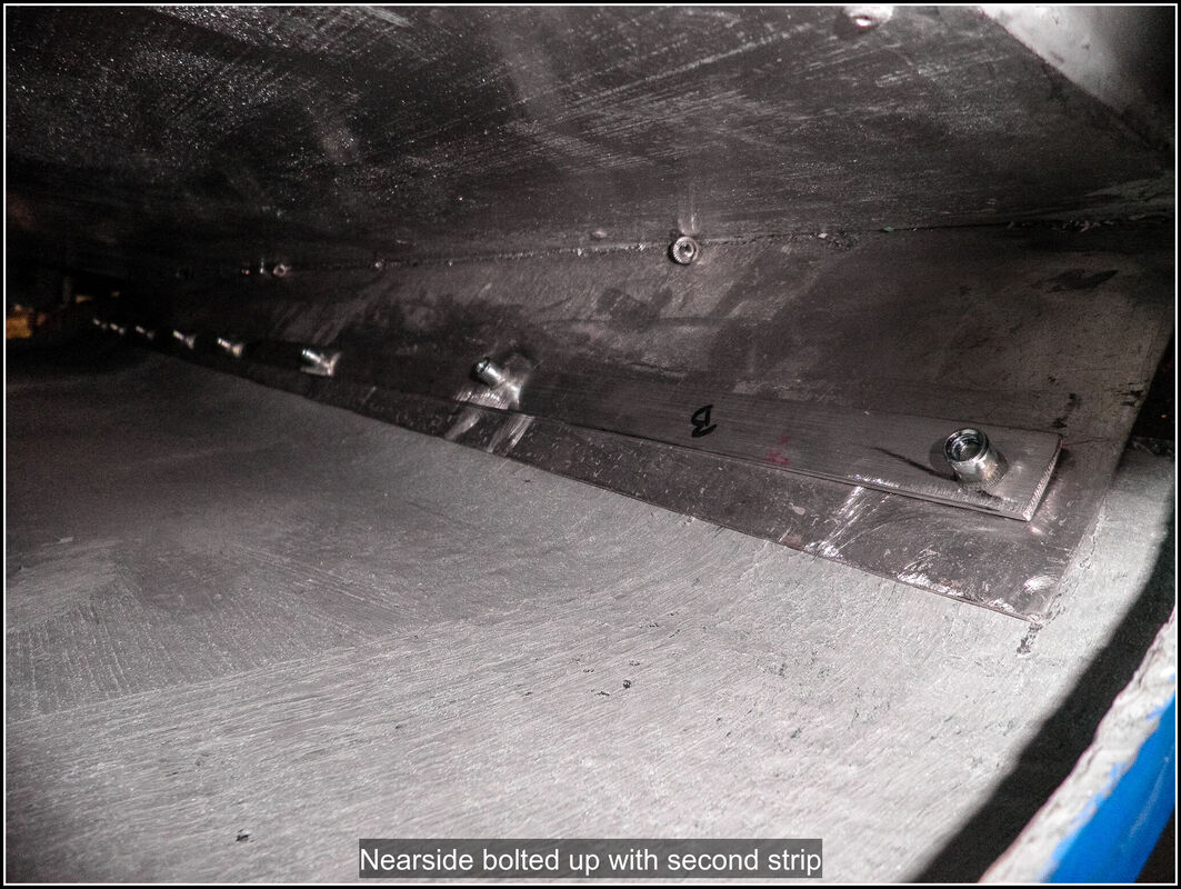
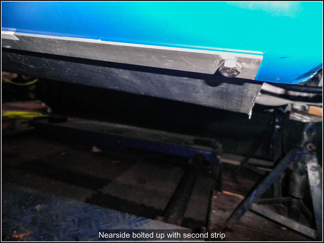
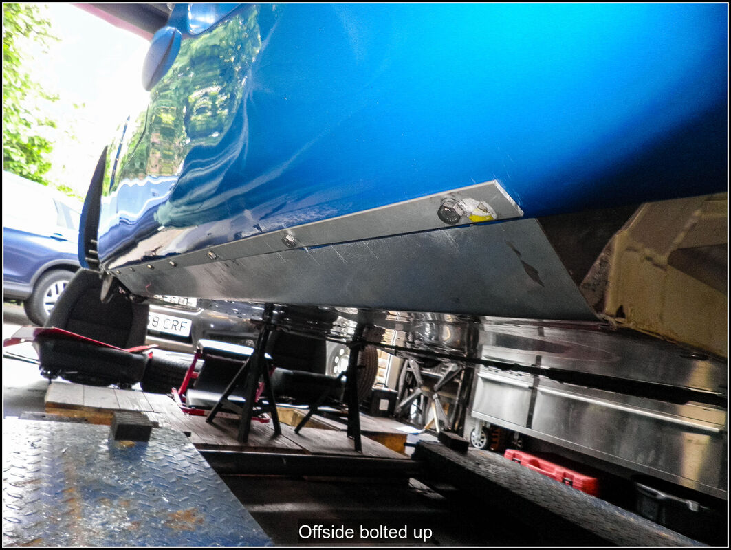
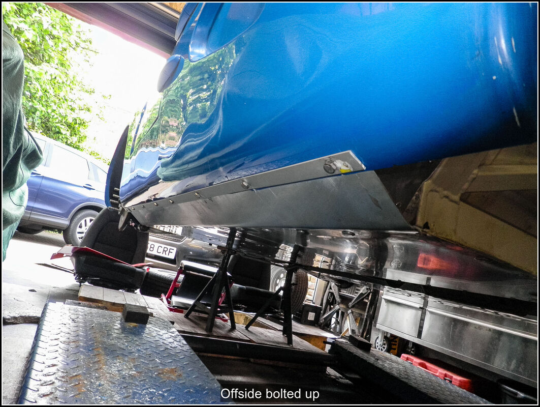
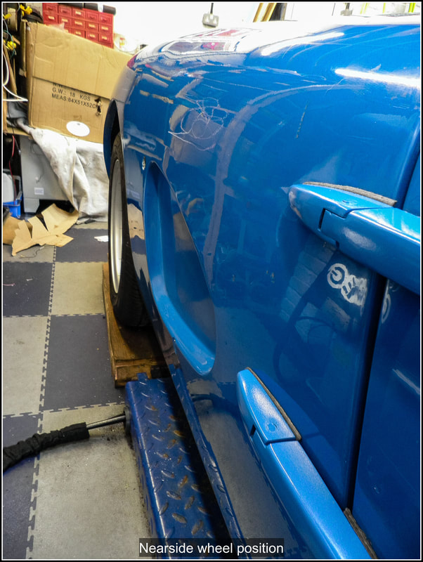
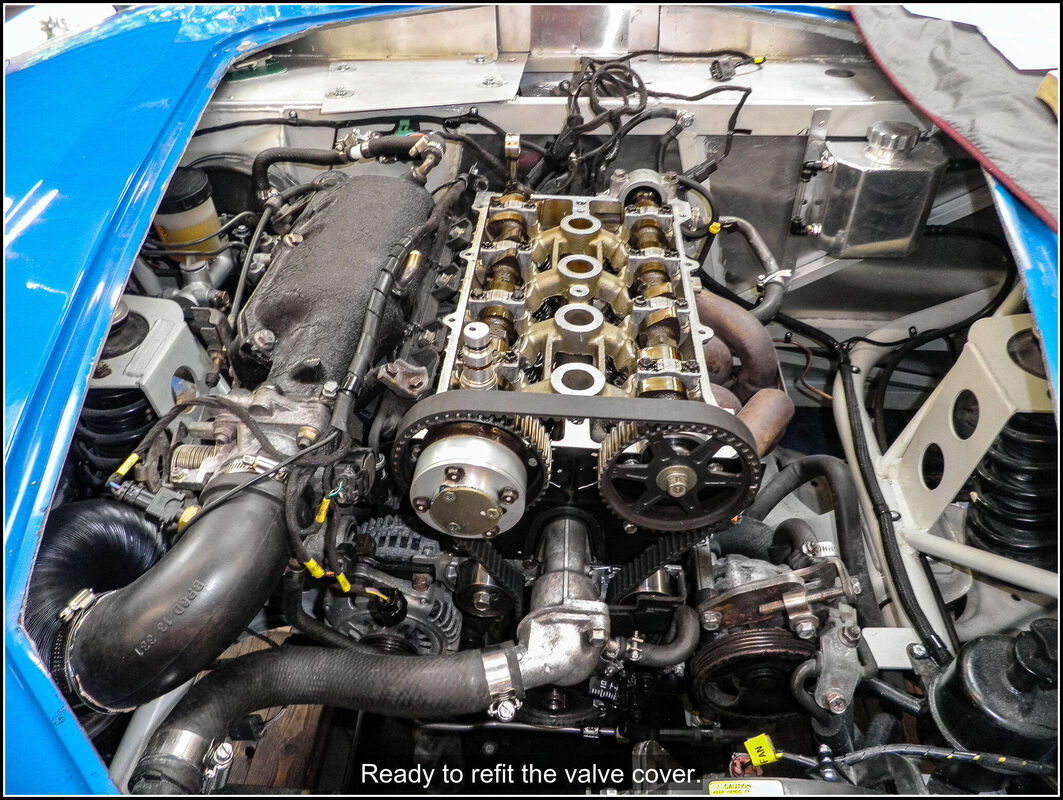
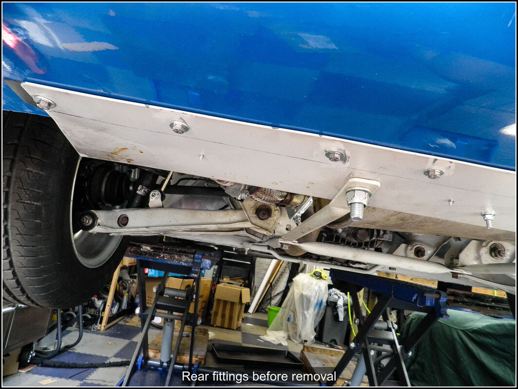
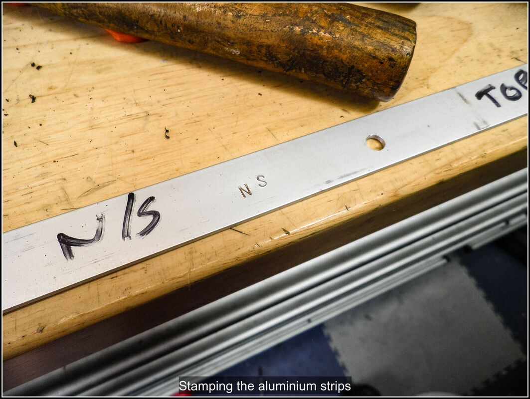
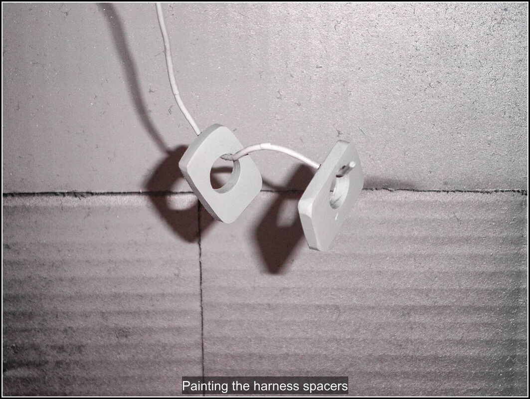
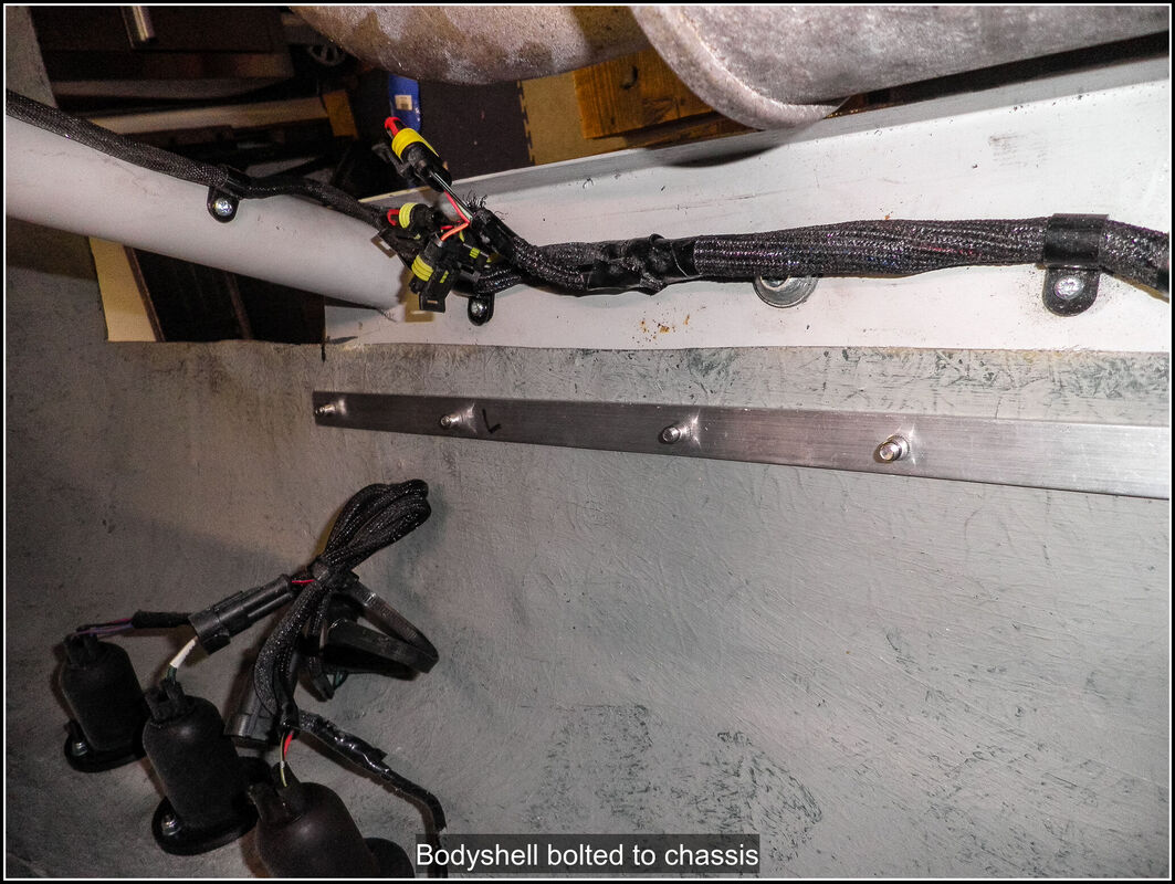
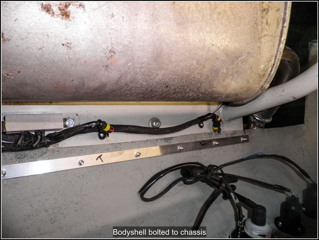
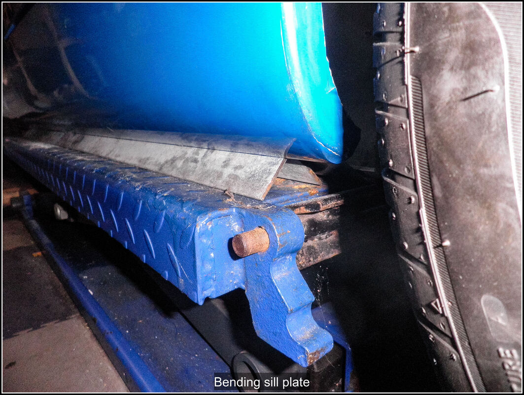
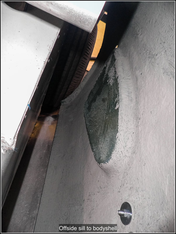
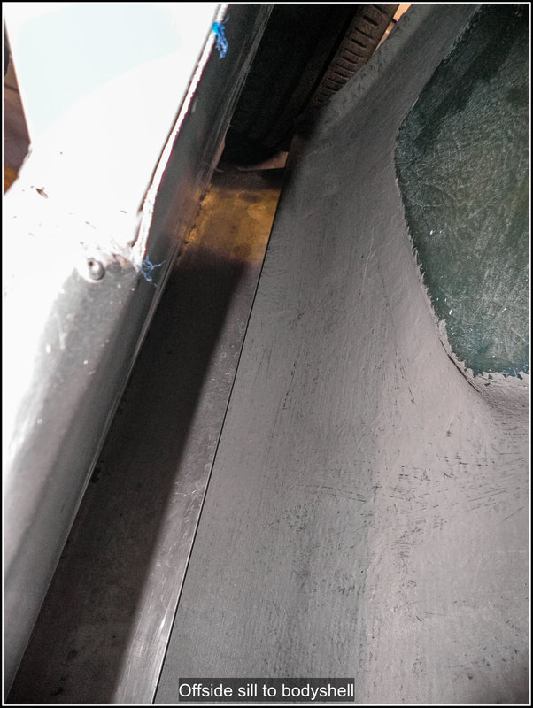
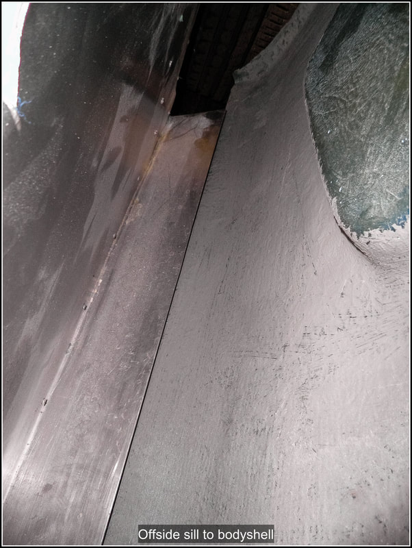
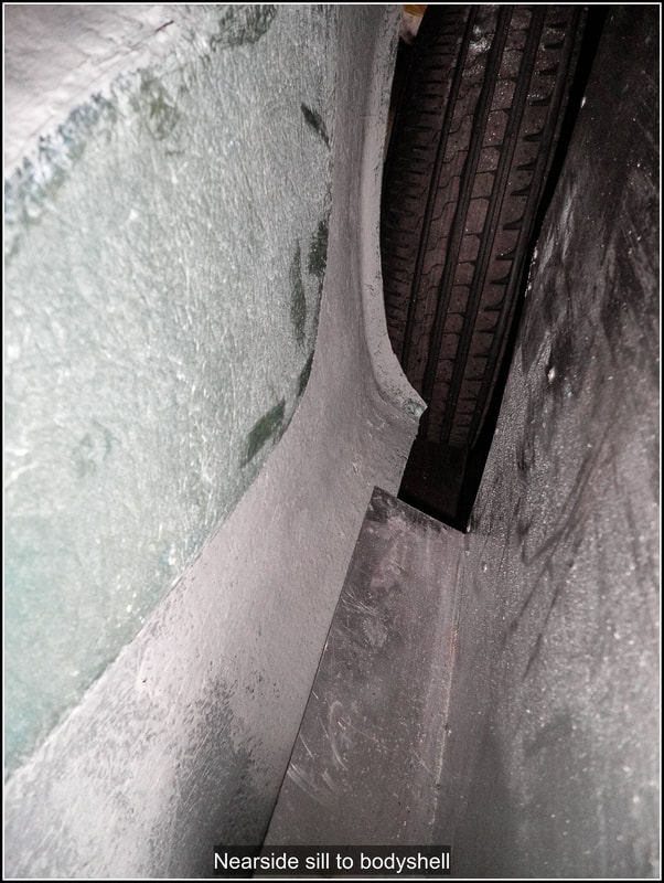
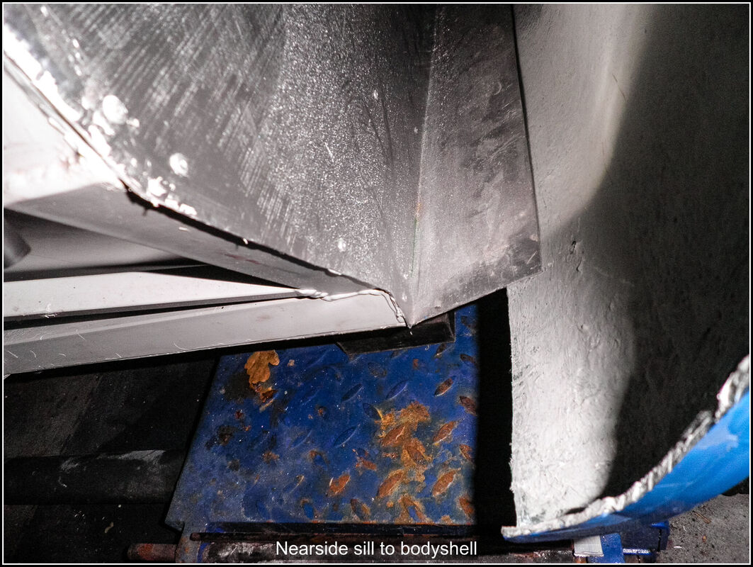
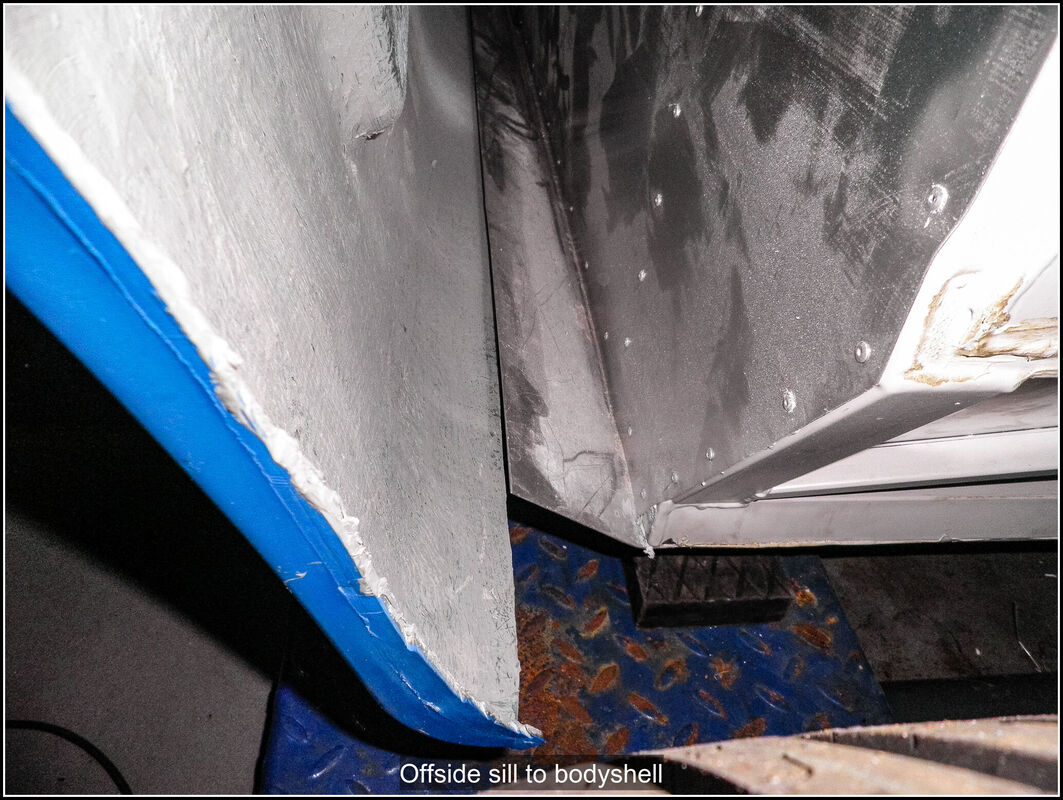
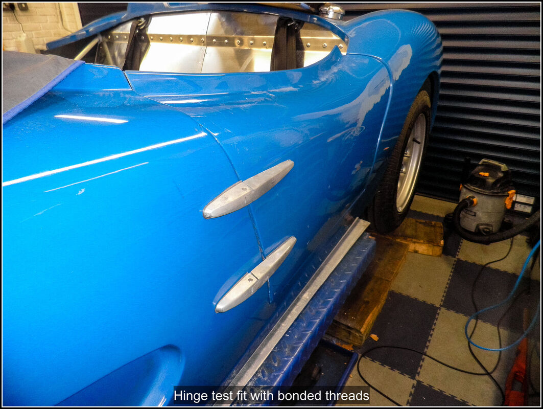
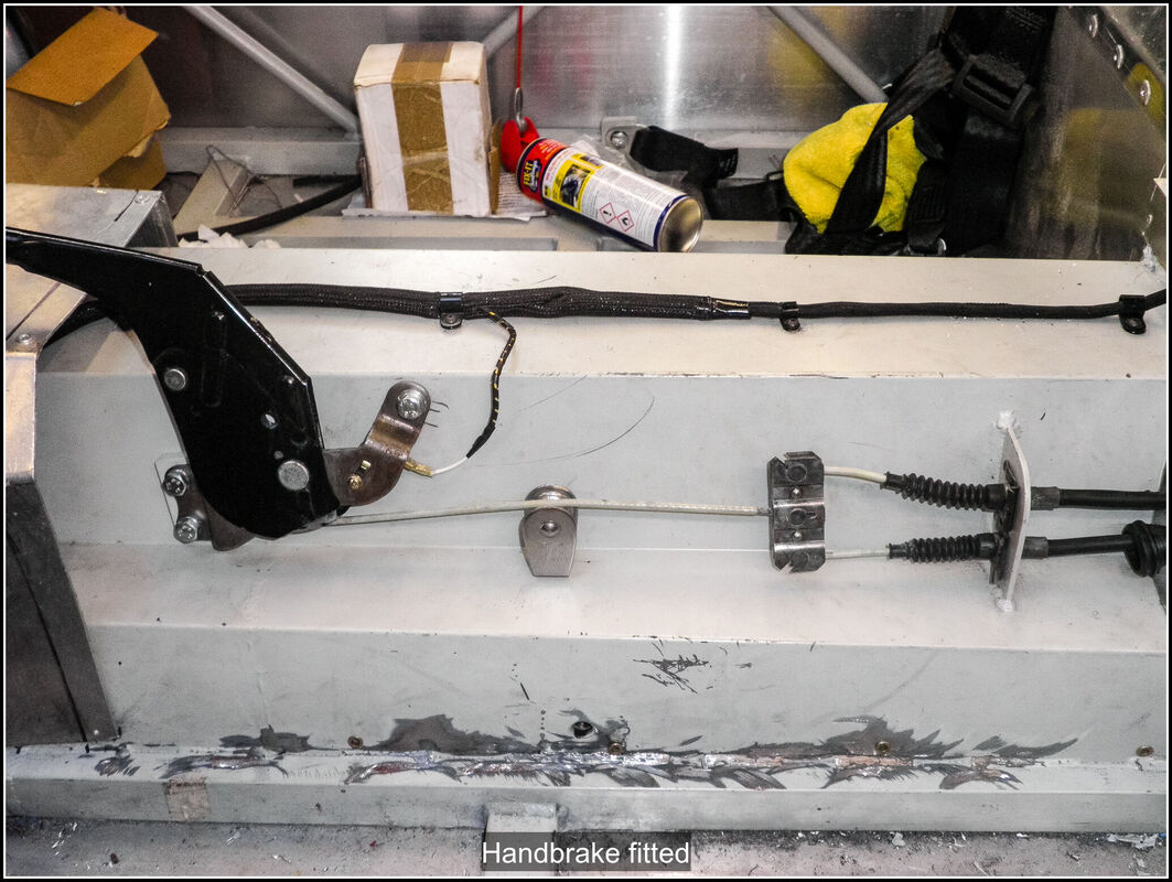
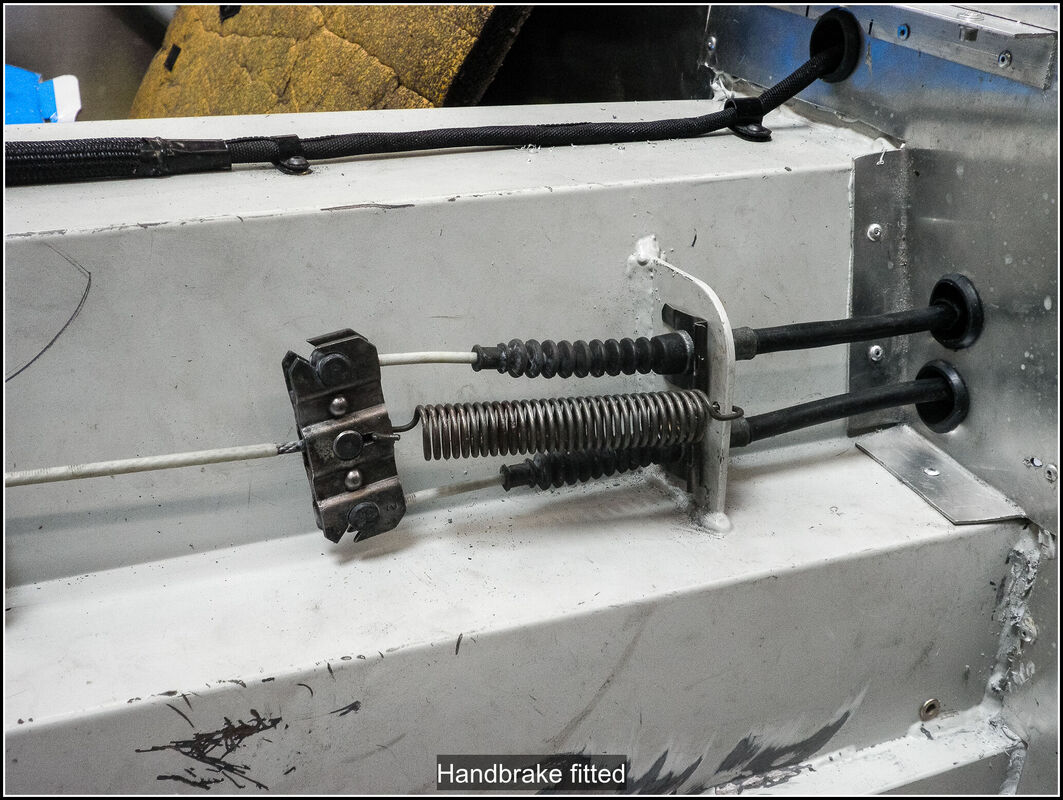
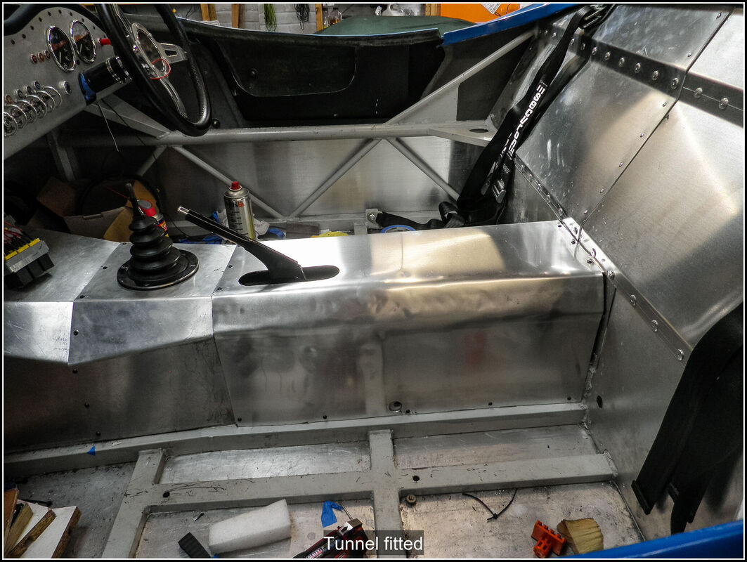
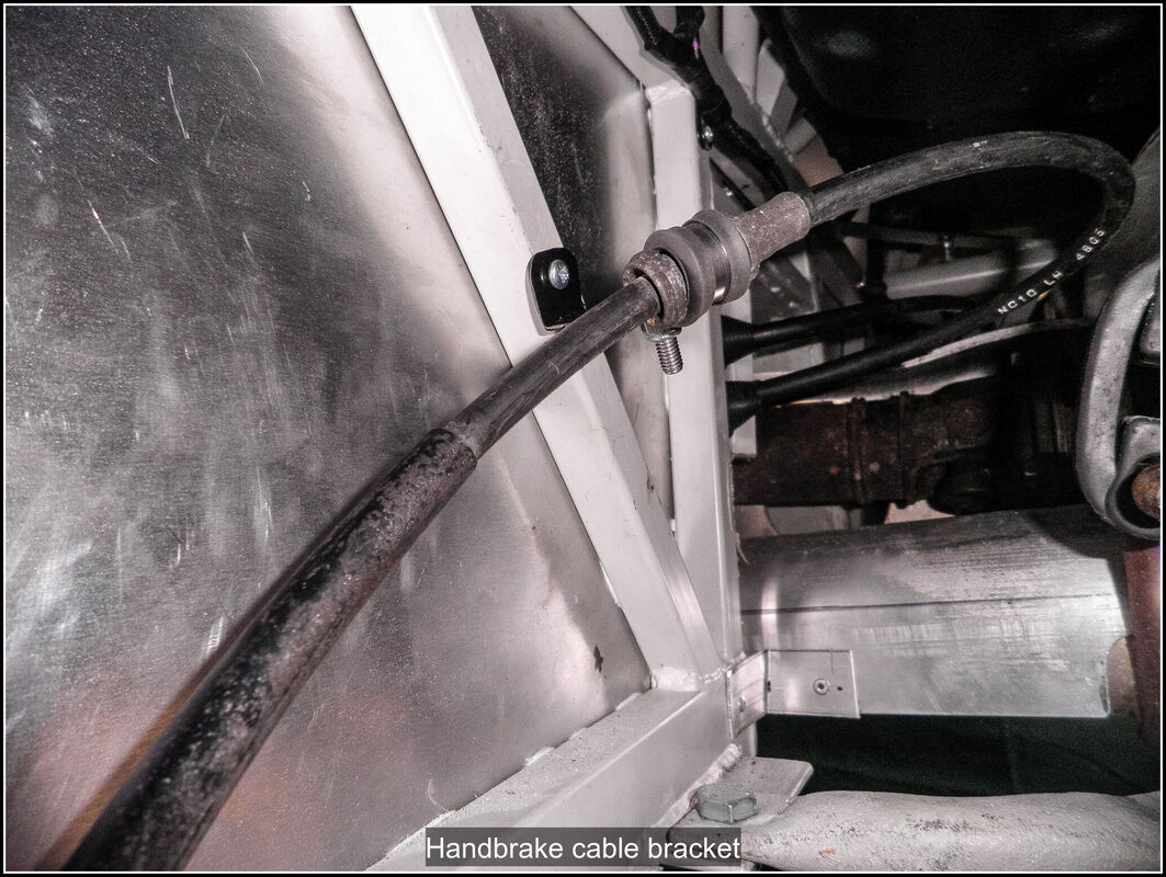
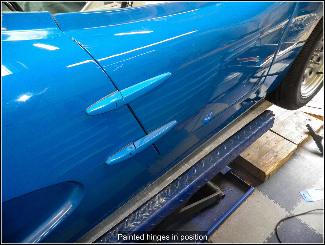
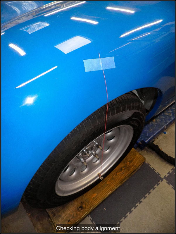
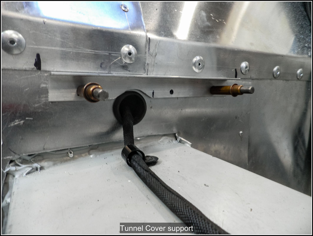
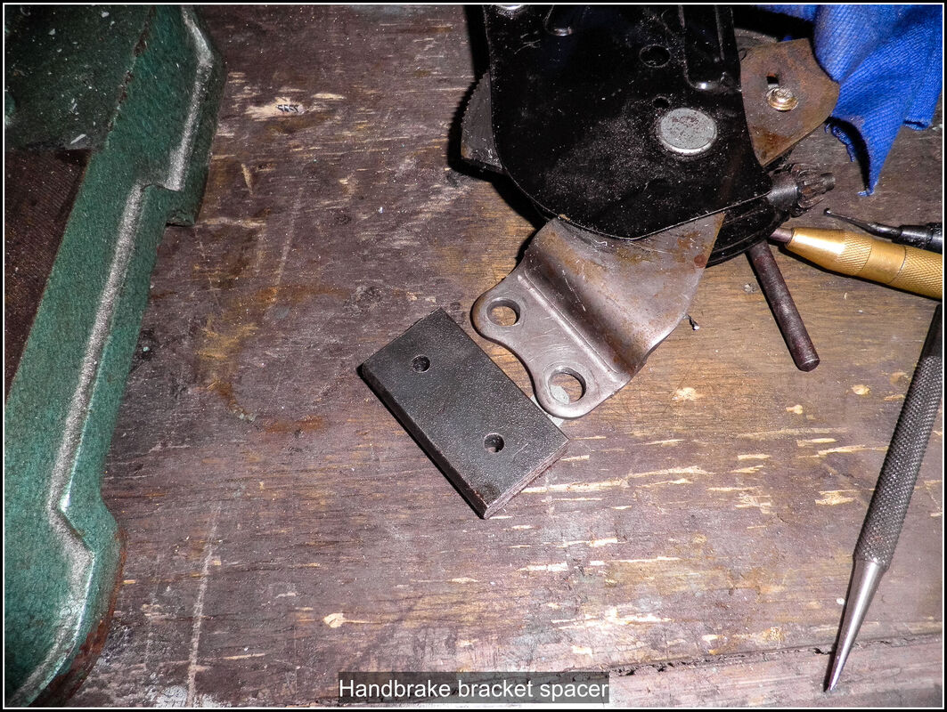
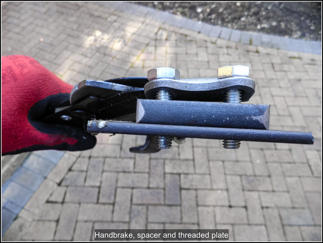
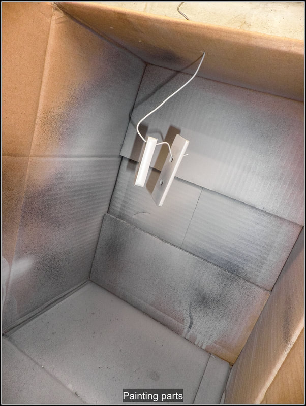
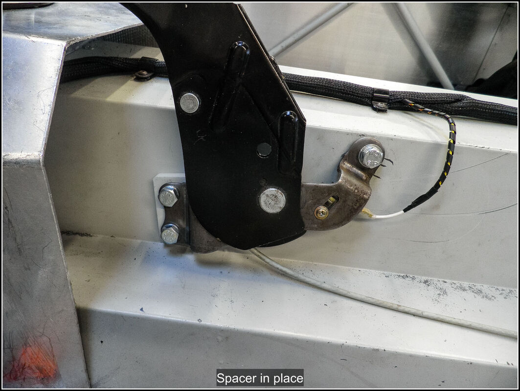
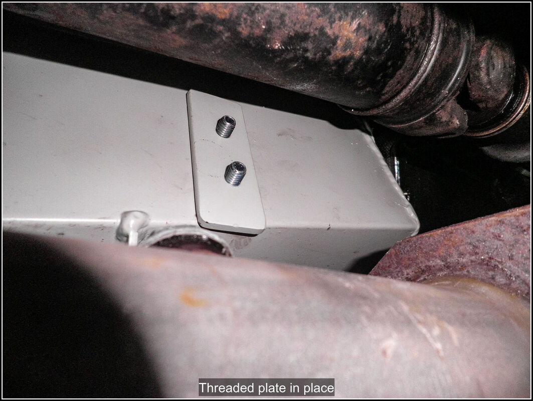
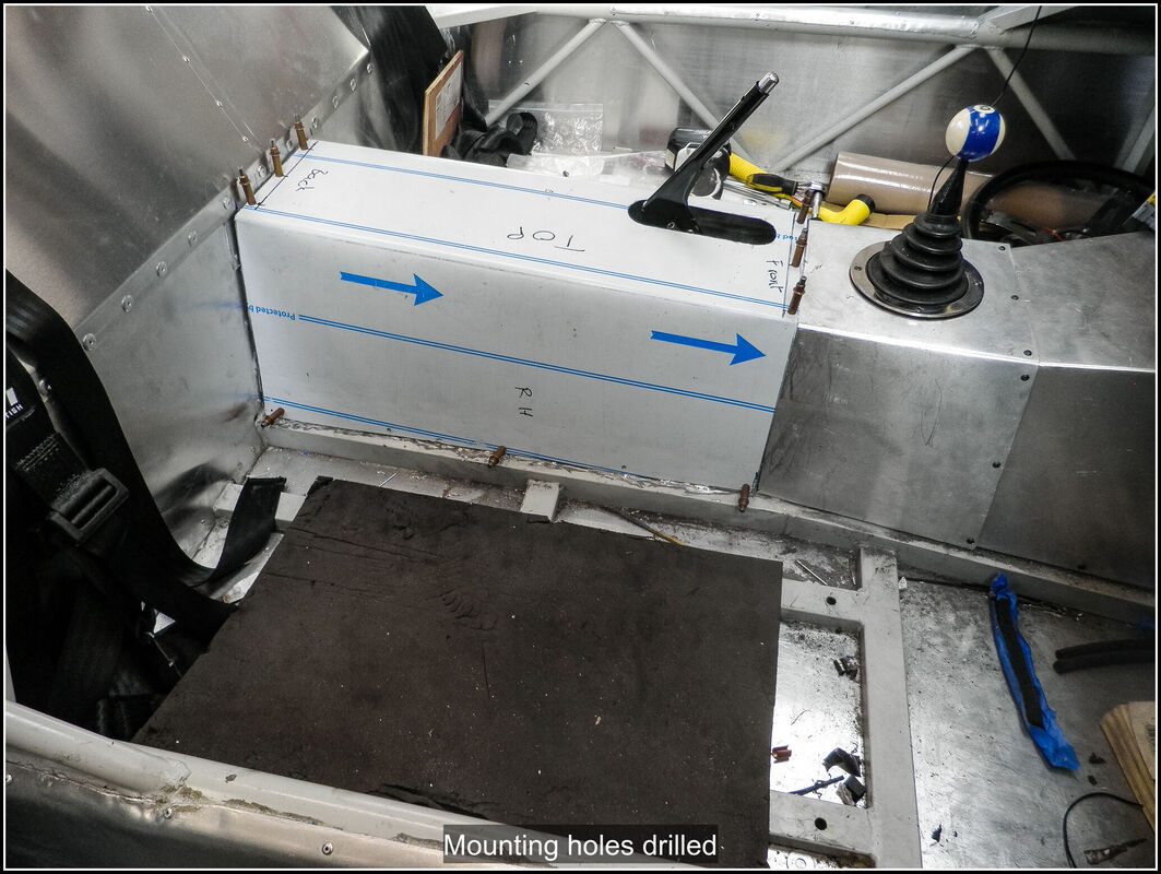
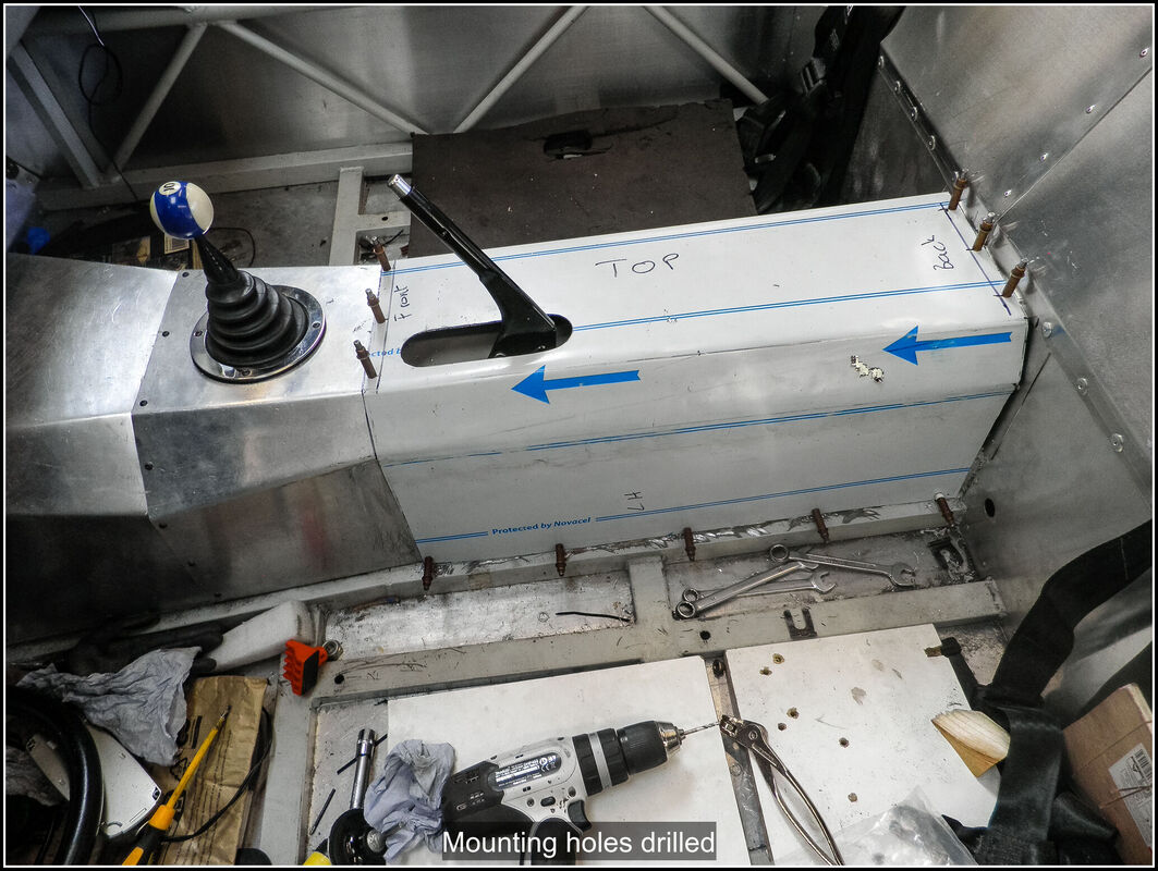
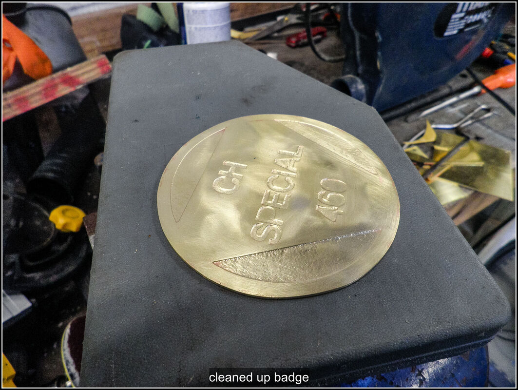
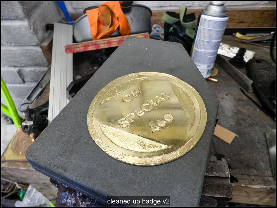
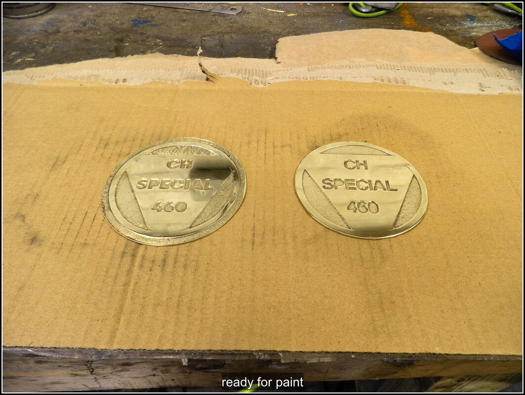
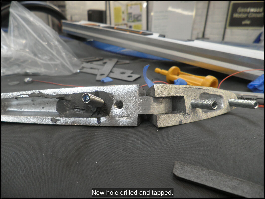
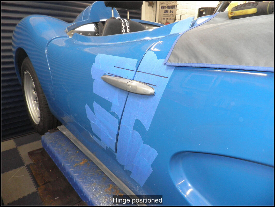
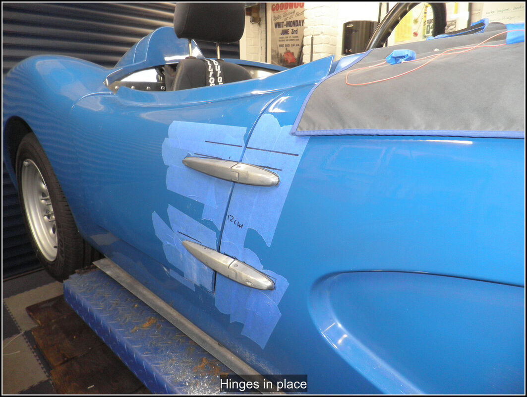
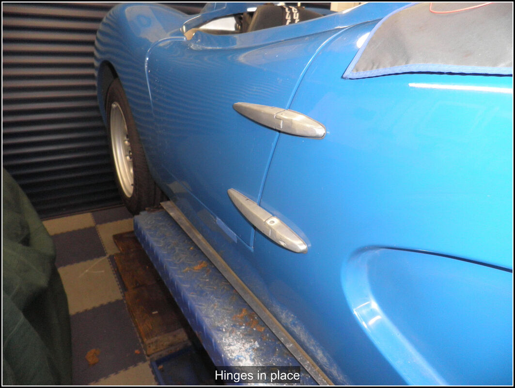
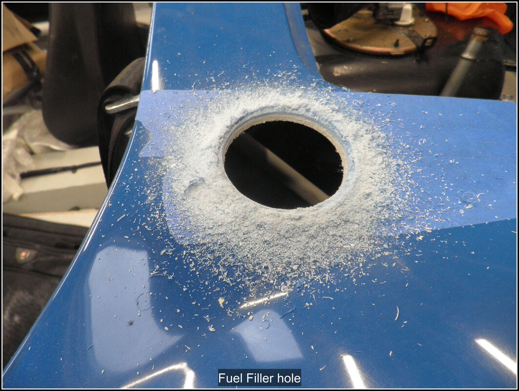
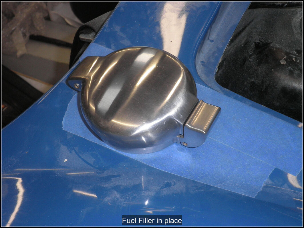
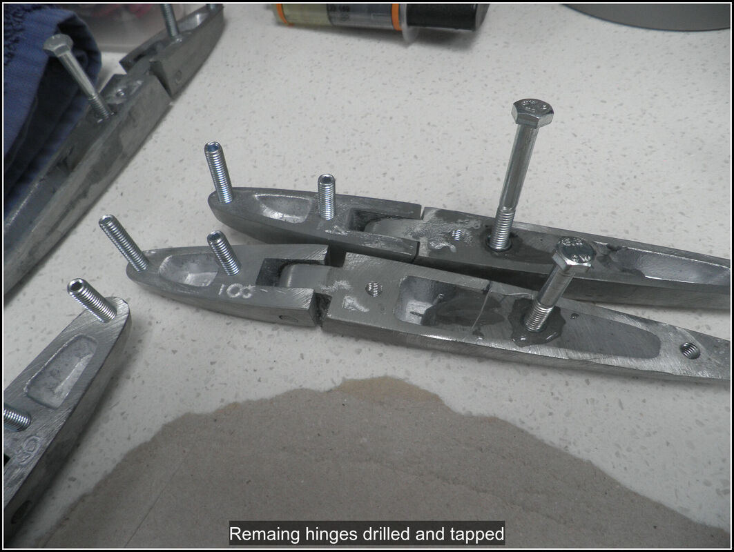
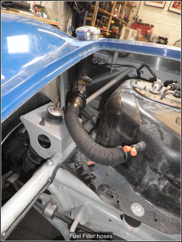
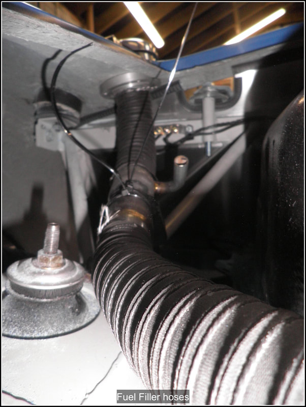
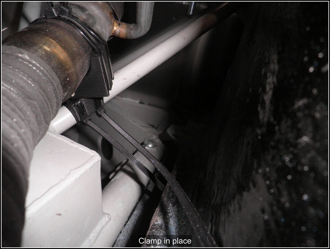
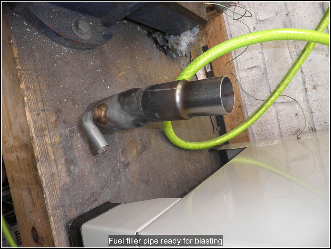
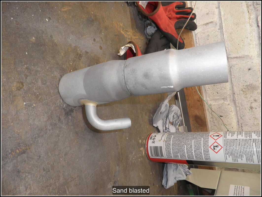
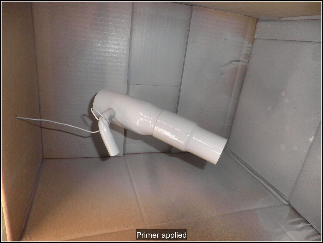
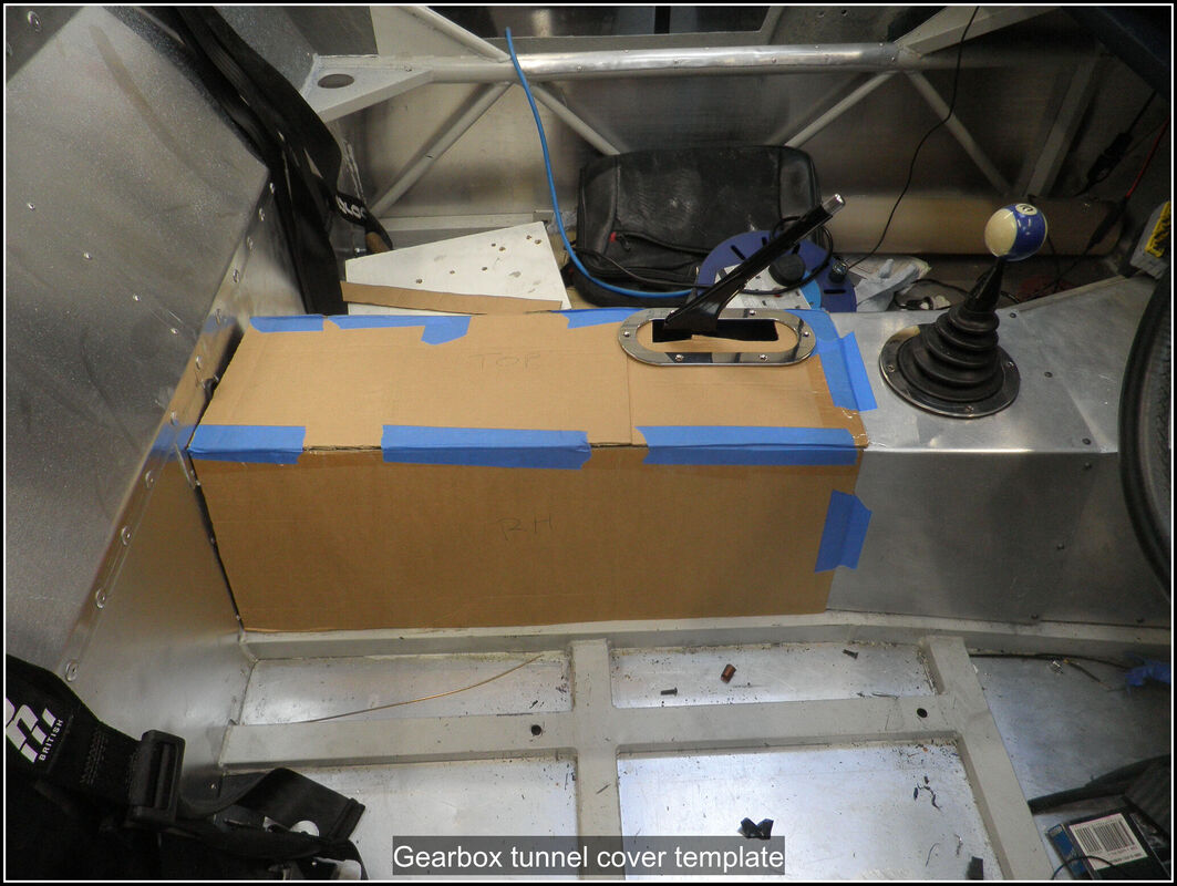
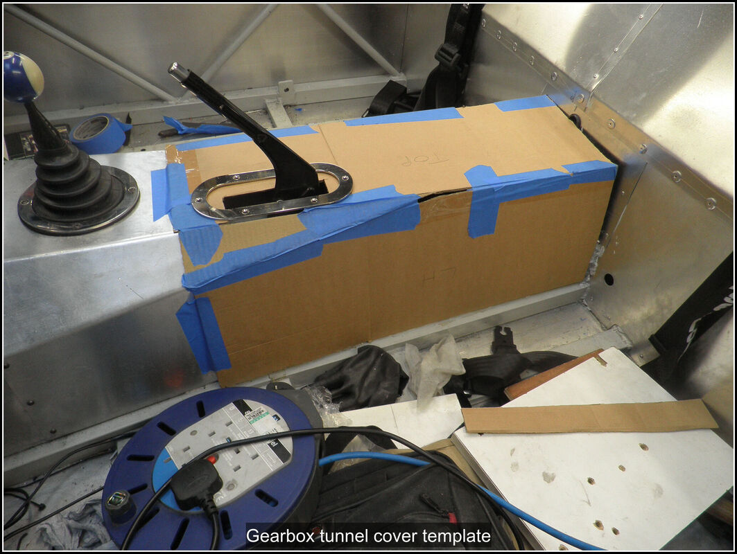
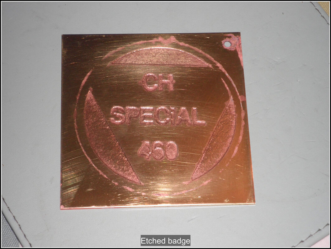
23 October 2023 The countersunk bolts arrived but they don't fit the handle (or hinges) on closer inspection it seems like the hex head countersinks are taller than the Phillips head type so they sit proud of the countersink. So I've ordered some Phillips head ones. Instead of finalising the lock fitting I decided I would clean up the fitment of the hinges by making up some plates to bolt onto inside the body. I have some slotted angle iron in my stores which is perfect for this sort of thing. I cut some lengths and then cut the angle off to make 2 plates and cleaned up the edges. The plates for the studs needed an extra hole drilling to fit the stud spacing. I made enough to do the other set of hinges I have for the bonnet. I degreased the plates, hung them up and put some hammerite on them. I also did a bit more flattening of the inside of the bonnet to help things sit flat. 29 October 2023 I tried my piece of wood again but due to the way the latch mechanism is offset the mounting on one side would foul with the handle mounting bolts. I made another piece of wood but could not figure how it would work. So it was back to the drawing board. I figured out that if I made it out of metal there would be enough clearance to avoid the bolts fouling. I came up with a design of a bracket each side that used the handle mounting bolts to hold them in place and then the latch bolted on the other side. After bending, drilling and shaping the metal I had 2 brackets that worked. I was able to use the wood as a former to bend the metal around. I reassembled the boot hinges and the lock and test fitted it. The latch was catching slightly on the boot apertures so I filed a recess so the lock cleared it. I had to add a couple of washers between the latch and the hinges so the lock could engage cleanly. With that all done I cleaned up the underside of the boot aperture so the boot seal would slide on a bit easier. I ran the boot seal all the way round and checked that the boot still shut (it did). I haven't figured what I've going to do with the boot seal where the latch is because it will interfere with the latch. I think I will need to glue something in place rather then have it secured on the edge. 11 November 2023 I got the car out of the garage for a short walkaround video. Then back in the garage so I could work on it. First job was to swap the other headlight retaining ring for the black one I bought to match the nearside. I noticed that the front indicator wasn't working, so removed the inidicator to find the bulb had popped out of the holder. Reseated and tested it and reassembled the indicator on the car. Next up was the aerial loop for the immobiliser which has been hanging loose in the car since it was fitted. I made a decision on where I wanted the aerial to be located. I wanted to hide it as much as possible and decided to make a small trim panel to enclose the aerial so I could secure it in the car. Cut some thin plywood to fit in the space I had decide on. I added to extra strips of plywood down the sides so it would not be flush against the panel. I wanted the wire to pass through the panel and come out the back and this gave me enough space for the wire. Next I drilled a hole for the wire to pass through the plywood and wrapped the connecting wire in tape to protect it. I secured the aerial loop to the plywood by drilling some holes in it and using cable ties to hold it in place. I glued some scrim foam over the top and then covered the whole panel in vinyl. Just need to secure the panel to the car and I can tick that off the list. Spent too long searching for the driving light covers I made way back when. I knew I had put them somewhere safe but as always happens I had forgotten where that safe place was! However I finally found them and rechecked the fit, the edge of perpex was a bit lumpy so I spent some time smoothing the edge out with a sanding block. I'm still undecided how I want to secure the covers to the car, so I spent a bit of time holding them up to the car but haven't really made up my mind. It will be some sort of screw and nut arrangement, the tricky part is how to secure the nut. 18 November 2023 Pulled off the nearside rear wheel to see what adjustment I could make to the rear body mounting. I want to raise it about 2mm to give a bit more clearance round the upper harness mounting. I will probably slip a washer under the mount to raise it but I'll need to bend the side mount slightly to allow that. I also need to glue the mounts to the underside of the body. Started to work on the fixings of the driving light covers. I spent some time shaping them more with the disc sander so they fitted better in the recess. I thought about the different options for fixing the covers, my preferred method was screws through the covers into the body but clearance at the back was not good in a couple of places. I decided to make up some alloy brackets. They will sit outside the edge of the recess and hold the covers in place. Cut some stips of aluminium and then shaped them on the bench sander, drilled a mounting hole and made a slight bend in them so they would push against the covers. I am going to paint the edge of the covers black or body colour and add some sort of gasket between the cover and the body. The brackets will have a something on the underside so they don't scratch the covers. 25 September 2023 Refitted the door once the Cold Weld had set and line it all up again. Played around with door seal samples to see what I wanted to use on the door, boot and hinge apertures. I found I can use the same seal type on all the apertures so once I new the size I ordered some online. I was almost ready to order some mini hinges for the boot and bonnet when Rob at Quantum posted pictures of some new internal hinges for the car. Just waiting to see when they are going to be available and how much they are going to be. 1 October 2023 Decided that today I would see if my car actually drove and if the speedo worked. Ran the car up to temperature then drove it down the road and back, nothing fell off and the speedo is working (it still needs calibrating). I noticed the fan didn't seem to be cooling the engine fully, this wasn't a problem before so I'll need to investigate that a bit. Engine seems to be running OK and I was able to adjust the idle down to 1000RPM, the closed loop idle still isn't working so I've disabled that until I can get it down to the tuners for the ECU to be properly mapped. Also notice my oil leak is back so I will need to investigate that again, hoping it's just a case of redoing the cam cover again with more sealant in the corner and maybe a fresh rubber gasket. Worked on getting the door seal fitted on the drivers door, the edge of the door need a bit of work to get the thickness consistent and straight all the way round the door apertures which I sorted with a selection of sanders. Once that was done I cut the seal to length and fitted it. I need something to tidy, seal the ends of the seal so I'll have a look around for some thing suitable or maybe 3D print something. 7 October 2023 Removed the nearside door, tidied up the door aperture, fitted the door seal and then refitted the door, seems like a good fit. Topped up the radiator, which only needed a little coolant, and then ran it up to temperature it seemed to be OK but I think I need to run it for longer to see. I wonder if the fan might not be running at full speed. Might try a test with a direct battery feed. I got on with securing some of the body wiring. I cut down some M4 bolts, to a length and then drilled the body and secured the wiring with some p-clips. The wiring to the side indicators needed some additional support, the wiring connectors I used have provision to slot on to a bracket. I cut and shaped some aluminium sheet to fit in the slot on the connector. I secured it to the chassis frame and slid the connector on to it. I added some more p-clips to the wiring on the front of the car to secure it. 14 October 2023 Managed to break the light fixing on one of my headlights last week so had to replace the bowl with a new one. Straightforward enough to unbolt and refit but I had to unpin the headlight connectors to get them through the hole. I had ordered some classic Mini hinges, so got on with fitting them to the boot lid. Started off by smoothing the edges of the boot lid to remove a few imperfections and remove any lumps using a small die grinder and some 180 grit sanding discs. I used some 2000 grit for smoothing out the gel coat around the outside where there were a few lumps. Then I spent some time marking up where I wanted the hinges, I ended up having them 20cm in from each edge. I used some masking tape so I could put some alignment marks on the bode to help everything line up. The hinges didn't come with any gaskets so I cut some out of gasket paper. I used the gaskets to mark the holes to drill in the boot lid then fastened them to the boot lid to mark the position on the bodywork and drilled those holes out. The bolts are are M6 so I drilled out to 7mm to give a but of wiggle room. The counter sunk screws supplied are designed to go into a steel panel so they a re bit short for the GRP panel so I've ordered some 20mm ones to replace them. But the boot lid opens and closes nicely. I then started on the boot handle/lock. I positioned it in the centre of the panel at the top and then moved it about until the locking mechanism would catch the lip in the body. I cut a 19mm hole out to fit the central bar and then filed it to fit the locating pegs. I drilled out the holes for the bolts on the handle as well. The latch bolt holes are in a different position to the handles and it needs to be mounted away from the panel so it can latch on the body work lip. I plan to bond a piece of wood to the inside of the boot lid that I can screw the latch to. Ordered some longer countersunk bolts for the hinges and extras for the handle. Ordered some threaded inserts for wood and also picked up some leather ammo pouches that I have a cunning plan for. 15 October 2023 Back to the boot latch mounting. The base of the handle was flat so I ground a slight curve on it to match the panel. I made rubber gasket to seal against the panel and iron out any imperfections. I cut a piece of wood to sit on the inside of the boot lid to mount the latch onto. I drilled clearance holes for the handle bolts and the shaft but the holes needed for mounting the latch overlapped the clearance holes I needed for the handle mounting bolts. I came up with an alternative design with a single hole for the lock shaft and then a cut out on one side to clear the handle mounting bolts. That seems to work much better. Still waiting for the counter sunk headed bolts so for now it is mocked up with some hex bolts. 25 August 2023 A few hours in the garage and I finished fitting the lock on the door. The bear claws I am using for the locks, handily have the mirror image bolt pattern for the fixings so I could use the wrong lock on the outside to give me the positions of the holes. Opened up the slot on the other door and fitted the lock in the same way. Bolted through the door with some M6 nuts and bolts. I might make up some plates from steel to go on the outside of the door to spread the load. Still managed to mess up the position of one of the holes so once I had drilled the right hole I filled the wrong one with some fibreglass filler. 28 August 2023 Back on the locks, I decided I wanted to make a plate to go on the outside of the door to help secure it to the GRP rather than just some washers. Found some flat bar and cut it to size and drilled out the hole pattern, then sanded it smooth and painted it black. I refitted the doors and temporarily bolted the locks in position with washers so I could look at how the striker was going to fit. I realised it was too thick for an M6 thread to be cut on it, so tried sanding it to thickness with a drill and belt sander but that didn't go to plan and ended with one end too narrow and the other too wide. Gave up on that and ordered some 6mm bar which I can cut the thread on and bend to shape. One of the things I've been thinking about is inner wheel arches and I'd seen a couple of YT videos of people making them out of ABS plastic sheet. I'd ordered a couple of sheets so I set to with cardboard and scissors to see what I could come up with. Got something I'm quite happy with, need to figure out how to secure it to the car. The edge of the arch is easy enough but it will need support on the inner edge or it is going to flap about. At the moment it just covers the area above the tyre, I might look at extenfing it in places to give more coverage. 24 September 2023 The 6mm bar arrived and I cut a 15cm length of it. Cut a thread on the end and then drilled a hole in the chassis gusset I could thread it through. I fixed a nut on the outside and tightened a nut on the inside to hold it in place. I then made a few bends in the bar until it was lined up with the lock. A bit of minor adjustment and the door locked (and unlocked easily). When I ordered the door locks I also ordered some thin plastic covered cable to act as the door release. I cut some off and looped it through the door lock and crimped it in place. I cut some short lengths of aluminium angle for a bracket and drilled a small hole for the cable and a larger one so I could bolt it to the other end of the door pocket. With the bracket in place I adjusted the length of cable and then crimped that end in place. I wrapped the crimps in some electrical tape to hide them. I added some heat shrink on the door striker to reduce any rattling when the door is closed. I repeated this for the other door so both doors now lock and unlock. I found a problem with the rivnut I had set in the top hinge had not fixed well in the hinge which prevented me tightening the hinge to the door properley so it kept sagging. I removed the door and hinge from the car. Pulled the rivnut out, and drilled the hole out slightly larger and deeper, then made up some Cold Weld and slid the cleaned up rivnut back in place, ensuring the hole and rivnut had a good coating of Cold Weld. Time to tidy up and let the Cold Weld cure. 16 July 2023 Decided to fit the seats so I could work on the harness fitting and routing. I fitted the offside one loosely to the chassis and then set about the nearside one. I dug out the mounting bars I'd made up some time ago and the bolts to mount the seats. Had a few issues getting the seat installed. I had to take it out and trim the Mazda seat belt mounting from the runners and also enlarge the bolt holes to the chassis to get it in position. I will also trim the offside one as I creates a nice bit of clearance to the transmission tunnel, there's also a tab that is used for the Mazda seat belts; it sticks out and I'm concerned it could rub on the harness. I tested the harness on the nearside seat and as far as holding me in the seat it works but the harness rubs on the headrest uprights. Also on the nearside there isn't enough room under the bodyshell to fit both harness mounts and my spacer. So I decided to move the harness mounts forward of the rear bulkhead. I used some 4mm steel flat bar and cut some lengths, drilled and shaped it so I could move the harness mounting position about 60mm forward. At the moment everything is loosely attached but this looks like it will help with the routing of the harness straps. 17 July 2023 I removed the offside seat and trimmed the runner on that side too. I refined the shape of the harness mounting plates and then cleaned them up and painted them. 25 July 2023 I bolted up the harness mounts and they seem to work well. Trial fitted the handbrake surround and gaiter. The gaiter will need some trimming later on, for now I trimmed enough so it sat correctly. I marked up the position of the mounting holes and drilled and fitted rivnuts to the tunnel cover. I positioned the ring and gaiter in place and marked where I needed to punch holes in the gaiter. Once the holes were punched, I had to resew one of the seams that started to come undone because of the hole punched in it. I did several trial fittings before applying contact adhesive to the gaiter and the underside of the ring. Then I bolted it all in position and left it to dry. Once it is dry I can trim the excess round the outside of the ring. 31 July 2023 Removed the handbrake gaiter surround but found the glue wasn't holding very well. So pulled it off and cleared the glue off then trimmed it back and rebolted it in place without glue. Bolted the fusebox back into place to tidy things up. I also finalised the switch that allows you to disarm the immibiliser when you get in the car. 23 August 2023 Haven't been able to get on with much recently due to summer car shows and meets as well as fixing daily cars for the family. Got out there for an evening and made a start on the door locks. Started by making up a piece of bar to use as the striker which will bolt to the chassis. It's just a length of bar with a 90 degree bend, at the moment it's much larger than it needs to be so I can trim it down once everything is finalised. I plan to put a thread on the end and bolt it through the chassis gusset that ANC added for this purpose. I used the bar to mark a position on the doors and cut out a slot to match the slot in the door lock. It's just roughed out at the moment. 15 May 2023 I did some measuring of the distance from the chassis to the outside edge of the body on each side. From previous checks I was happy with the natural position of the nearside. The offside needed pulling in slightly which I did with a ratchet strap round the body. Once I was happy with the position it was time to drill some holes. I started with some aluminium flat bar and marked out holes at regular intervals and then drilled some pilot holes. Then I clamped the bar in position on the outside of the body, clamping it to the body and floorplan. Once I was happy with the position, I drilled through the pilot holes and through the body shell and floor plan. I then enlarged the holes to fit an M5 bolt and drilled the floorpan to take an M5 rivnut. I fitted the rivnuts to the floorpan and then bolted through the aluminium strip, body and into the rivnut. This was initially successful but the rivnuts didn't have a sufficient grip on the floorpan, I think the floorpan was a bit too thin and they worked loose. I drilled them out and left it while I had a think. 22 May 2023 My revised plan was to have a second strip of aluminium bar and add rivnuts to that and then clamp the body and floor pan between the 2. It's much easier installing the rivnuts in the bar while it is on the bench. I increased the size of the bolts and rivnuts to M6. I marked out and drilled the second piece of aluminium using the first as a guide, making sure I marked up the front and back ends of the strip. I drilled the holes out and added the rivnuts and for additional peace of mind I added some epoxy glue while I was inserting the rivnuts. Fitted the nearside and then double checked the measurements with the offside. I repeated the operation on the offside so I have now got both sides secured. I've not added the rubber strip yet but I will do that once I have bonded the aluminium strip to the body and the inside of the floorpan. The strips will get a bit of shaping to tidy them up as well. 26 May 2023 Decided to have another look at the rough running of my engine. Checked and found one of the air hose clamps was restricting air flow a bit so fixed that. Also played around a bit with the cam position sensor wiring and added more fuel. Started it up and it seemed to run much better although idling very high I suspect that is due to all the fiddling with the idle speed and air bleed screws. I let it come up to temperature and it seems to be fine although it stalled a couple of times. Very puzzling. However it seems I have another oil leak, it's dripping off the front of the oil pan so I hope it's not a problem with the crank seal again. 4 June 2023 Decided to investigate the oil leak, I started the engine and ran it for a bit and sure enough the oil is dripping off the lip behind the crank pulley. Removed the valve cover, front cover and timing belt and crank pulley. Crank seal looks perfect and there doesn't seem to be any oil around the seal, it seems to be coming from higher up the engine. Removed the cam sprockets and timing back plate and I can see oil has been running down the plate. Looks like I haven'y sealed the valve cover properly. Cleaned up the oil and started to reassemble the front of the engine but ran out of time before I could get the timing belt back on so that is for next time. 29 June 2023 Got the timing belt back on timed the engine lots of checking. Finished replacing the rest of the components I removed, taking care to put in a good sealing of RTV on the valve cover. Torqued everything down. 1 July 2023 Fired up the engine and everything good, warmed it up and so far no leaks! 9 July 2023 Removed all the body fastenings so I could lift the body enough to remove the harness bolts behind the seat. I had previously put them in with the bolt pointing down but with the body in place you can't remove them. I need to turn them round and insert them from the bottom. Whilst the bolts were out I painted the spacers so they don't rust in future. Removed the back box so I could fix the small exhaust leak between the flexi joint and the back box pipe. Cleaned up the joint and applied exhaust paste and refitted the exhaust. Started up then engine to warm things up and cure the exhaust paste. Leak fixed so another thing to tick off the list. While the fixings were off I stamped the aluminium strips with N/S O/S F(ront), R(ear) and L(eft) and R(ight) so I didn't get things confused when refitting. Refitting the body fixings proved quite tricky getting everything lined up. I fitted the rubber strip between the body and floor pan on the sides which proved tricky. Ran out of time to complete the offside, which was being particularly awkward. I've not bonded the aluminium in place yet, hopefully when it is, getting things lined up will be easier. 9 May 2023 The pipe for the petrol tank vent has arrived so I fitted that and made a bracket to support it in line with IVA recommendations. I then started on fixing the rear sill to the body. I cut a length of aluminium flat bar and then marked it up and drilled pilot holes in it down the centre. I placed it in position on the inside of the boot and clamped it all in place so it couldn't move and drilled the holes through the body and the sill, using some long pop rivets to ensure the holes kept alignment while I completed drilling all the pilot holes. I took the aluminium strip and drilled it out and fitted M5 countersunk rivnuts to it. Next up was to enlarge the holes in the body to fit the M5 bolts. I have a thin strip of rubber to go between the body and sill to keep rattles to a minimum which I hole punched for the bolt holes. Finally I fitted the rubber strip between the sill and body and bolted up through the sill, body and into the aluminium strip to secure it all together. 13 May 2023 Did some measuring of the body sides to the floorpan to see how even things were and how much bending would be needed. Back to schoolboy Pythagoras to calculate angles. The offside was a bit different to the nearside mostly at the rear and the bodyshell needs pulling in towards the chassis to even things up but I'm happy that the bodyshell is pretty central on the chassis. Now to bending the sills up to meet the body. I placed a piece of angle iron on the scissor lift and removed the rubber blocks, then I gradually raised the lift until the angle iron was just touching the sill. I then adjusted the position so it was outside the chassis and parallel to the chassis. I then raised the lift and allowed the angle iron to bend the sill, I had to stop when it touched the bodyshell and pull the bodyshell out and around the sill so I could bend it up a but more so when released it laid gently on the inside of the bodyshell. Then I repeated on the other side. That seems to have worked well, just need to pull the front offside wheel arch in towards the chassis to even things up side to side. I plan to bolt the bodyshell to the sill in a similar way to the method I used for the rear of the car, but I will have something on the outside to spread the force on the fibreglass, I also need to figure out the order of operation so I get all the holes to line up. 4 April 2023 Did a test fit of the hinges with the bonded in threads and that seems to work much better, no issues tightening them up. Took them off again so I could paint them. Rubbed them down and wiped them clean then etch prime and a coat of body colour. 29 April 2023 Fitted the handbrake cables again and added a pulley wheel to lift the cable up slightly so the equaliser didn't drag on the tunnel. Fitted the return spring and adjusted the handbrake. 4 May 2023 Cleaned up and repainted around the gearbox tunnel where I had ground down the welds. Added the brackets to support the handbrake cable under the car. Fitted the doors again with the painted hinges and adjusted the door fit. Seems pretty good, not perfect but pretty good. Did a bit more trimming on the gearbox tunnel so I could fit the harness to the sides of the cockpit, I needed to enlarge the hole as I didn't want it pinched by the hanrness fixing. Spent a bit of time measuring up to ensure the body is sitting evenly on the chassis, I did this by dropping a plumb line from the wheel arch down to the centre of the wheel and measuring from the hub out to the string. Then I marked the position on the rear body and chssis plate. I think I'm almost ready to start fitting the body. I will do a few more checks before I start and I walso want to review my plan for bolting rear and side sills to the body. 27 March 2023 Put my second badge design in to etch. Did some more work on the tunnel cover template, got it to where I was happy. Cut out some aluminium sheet and bent it on my Workmate , once the initial bends were in I removed the handbrake so I could get the fitting finished before I cut the hole for the handbrake. Started making the adjustments to get the fitting perfected but still a way to go before its done. Thinking about making something to support the tunnel so it can withstand being leant on to get in and out. Took the badge out of the etching solution cleaned it up and removed the vinyl resist. Very happy with how it's come out. Next job is to cut it out to the final shape before I paint it. 6 April 2023 Trimmed the badges to size on my bandsaw and then sanded it smooth round the edge. Cleaned out the etched areas with a scotch brite wheel and then polished up the brasss. Applied some etch primer and then some paint matched to the body shell. I applied this all over as the plan is to sand it back to leave the etched area in blue. I cut some aluminium angle to length and riveted it to the rear bulkhead to give me something to secure the gearbox tunnel to. 7 April 2023 I wanted to improve the handbrake mount so I took it apart and replace the nuts I was using for spacers on the front bracket, with a piece of solid steel. I decided to replace the rivnuts I had put in with a piece of flat bar that I drilled and threaded that would sit the other side of the gearbox tunnel. Cleaned them both up and applied primer and chassis colour to them. Applied some more colour to the badges, tryin to fill the etched areas. Removed the handbrake cables as I wasn't happy with them and I plan to order some replacements. 8 April 2023 Bolted the handbrake in place with the new fixings. Checked the position of the handbrake was still OK on my cardboard template. Marked up the gearbox tunnel up with the position of the handbrake and cut it our with my nibbler. Trimmed the hole so it matched the trim ring I have, using a combination of files and flap wheels. Put the tunnel in place and then marked and drilled holes in the top surface and through the panels underneath, held them in place with Cleco fittings Marked up the bottom edge and drilled those in preparation for securing them. Removed the panel again and added m4 rivnuts to the body ready to secure it. Ordered more M4 dome head bolts to secure the rear tunnel, a pair of handbrake cables and some press studs that I will use to secure trim to the tunnel. 27 February 2023 Added JB Weld to all the hinges as they will all need additional holes. I sanded the JB Weld flat, I held the hinge up to the door marked the poision for the hole on the hinge, using the penny washers I want to use. Then I carefully and drilled and tapped the hole for the new screw position on the top hinge. I punched a hole in the gasket, for the new hole. With the door still secured in position, I used the gasket to transfer the new hole position, on to the door and then drilled the hole carefully to avoid hitting the body. I completed the same exercise on the lower hinge. The hinges came supplied with studs, but using them on the door attachment would interfere with the closure so I found some bolts to use instead, shortening where needed. 12 March 2023 The replacement MAP sensor arrived so I hooked it up and tried the engine again, the ECU is seeing the MAP and getting a feed from it but something is still not right. Reached out to some tuners to see if someone could help me but it looks like I will need to make a trek. 18 March 2023 Found that one of the studs on the door had snapped off. IT had snapped flus so I cut a slot with my Dremel so I could unscrew it. Fitted the passenger door hinges. I took all the doors off and lengthened the holes to give me a bit more adjustment. The fit in the aperture nicely but the bottom edge is a little proud so I think I need to pack out the bottom hinge a bit to push it back. I marked out the position for the filler cap, taking care to allow for the mounting ring. I cut out an undersize hole then ground it out to size with a flap wheel. I will need to make something to hold the filler pipe I modified before. I a clamp to hold it to one of the chassis rails should work. It will need to hold it at a slightly different angle. 20 March 2023 Designed a clamp to hold the filler pipe and printed it off on my 3D printer. I made it in 2 halves which will be joined by a bolt so it can swivel and will be secured using tie wraps. 25 March 2023 Redsigned my bonnet badge to make it simpler and the text more chunky, popped into rLab and printed off some vinyl and applied to my new braas blanks. 26 March 2023 I cut down an empty milk bottle to hold the salt water for my etching. I drilled a hole near the edge of the badge and passed some steel wire through it then sealed it up with electricians tape. I put it in the salt waater with a steel cathode and turned on the battery charger and left it to fizz away. I had to replace the steel wire after an hour as it had dissolved due to the electical etching process, so I found some thick plastic covered electrical wire and used that instead. Removed a bottom hinge and padded it out with a second gasket which seemed to line up the door with body nicely but it revealed a problem with the thread I'd cut in the JB Weld which stripped. I don't think it is really up to the job. I decided to try putting in a threaded piece of metal. I thought about bonding a nut in there but decided to use a rivnut instead as it was simple to do. I just had to drill the hole out oversize and cut off the flange on the rivnut and I could epoxy it in place. I decided to do all four hinges. While the glue was curing, I got on with finalising the fuel filler hose. I already had the necessary flexible filler hose so it was a case of cutting the hoses to length based on the position of the modified filler adapter. I then took it all apart, sand blasted the metal section and primed and painted it black. I removed the drivers seat and made a start on templating the last bit of the gearbox tunnel using some cardboard. Quite happy with the general look but it needs a bit more trimming. After about 7 hours of etching I removed the badge, removed the vinyl and cleaned it up. Very happy with the depth of the etching, I plan to fill the etched areas with paint and the sand it back to leave the brass showing through. I've another slightly different design that I want to try too and then I'll paint them both up and see how they look. |
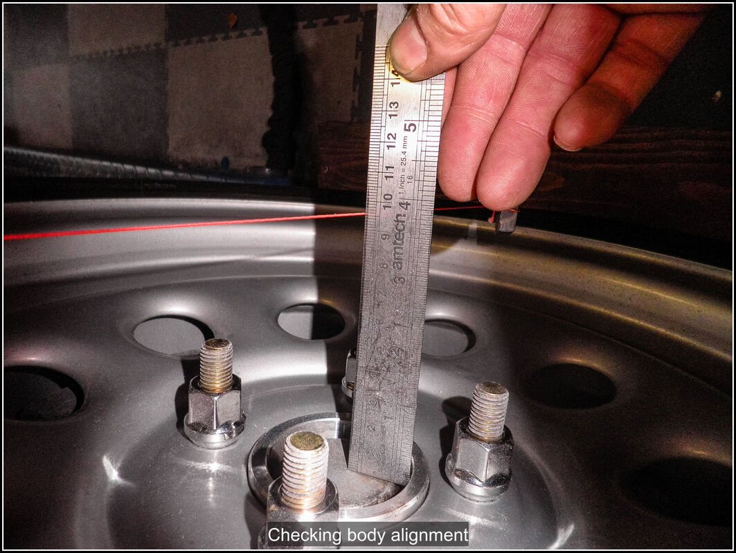
AuthorThis is my first kit car although I've messed about with cars all my life. Archives
November 2023
Categories |


 RSS Feed
